background image

3

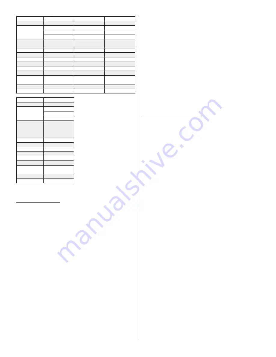
SPECIFICATIONS S163

S253

S418

HP

0�5

0�5

0�5

SYSTEM CAPACITY

40 PSI 163 GALLONS

28 PSI 253 GALLONS

18 PSI 418 GALLONS

PRESSURE SWITCH

FACTORY SET AT 
30-40 PSI

FACTORY SET AT 
23-28 PSI

FACTORY SET AT 
13-18 PSI

CFM

2�21 @ 10 PSI

2�21 @ 10 PSI

2�21 @ 10 PSI

PUMP

1 CYLINDER, OIL FREE 1 CYLINDER, OIL FREE 1 CYLINDER, OIL FREE

CYLINDERS

CERAMIC COMPOSITE CERAMIC COMPOSITE CERAMIC COMPOSITE

VOLTS

115

115

115

PHASE

1

1

1

RUNNING AMPS

4

4

4

BREAKER SIZE

15 AMP 
RECOMMENDED

15 AMP 
RECOMMENDED

15 AMP 
RECOMMENDED

DIMENSIONS

10” X 9�5” X 14”

10” X 9�5” X 14”

10” X 9�5” X 14”

WEIGHT

21 LBS

21 LBS

21 LBS

SPECIFICATIONS S164

HP

�5

SYSTEM CAPACITY

40 PSI 163 GALLONS
18 PSI 418 GALLONS
10 PSI 810 GALLONS

PRESSURE SWITCH

FACTORY SET AT 
10-20 PSI
MINIMUM 
DIFFERENTIAL: 5 PSI

CFM

2�21 @ 10 PSI

PUMP

1 CYLINDER, OIL FREE

CYLINDERS

CERAMIC COMPOSITE

VOLTS

115

PHASE

1

RUNNING AMPS

4

BREAKER SIZE

15 AMP 
RECOMMENDED

DIMENSIONS

10” X 9�5” X 14”

WEIGHT

22 LBS

SAFETY
DEFINITIONS


!

DANGER

: Indicates a hazardous situation that, if not 

avoided, will result in death or serious injury�


!

WARNING

: Indicates a hazardous situation that, if not 

avoided, could result in death or serious injury�


!

CAUTION

: Indicates a situation that will or could cause 

minor injury or property damage�

GENERAL PRECAUTIONS

Read the Owner’s Manual before operating�


!

DANGER

Do not use compressed air for breathing air applications� 
Beware of high voltage: disconnect lockout/tagout elec-
tric supply before servicing� 
Ground compressor per codes�


!

WARNING

Beware of high-pressure air: do not bypass, modify, or 
remove safety/relief valves� 

Beware of hot surfaces: allow unit to cool before servic-
ing� 
Do not operate with safety guards removed�


!

CAUTION

Never operate the compressor near flammable liquids or 
vapors� 
Do not direct the air stream at body� 
Drain tank air weekly to decrease risk of bursting�

NOTE

: Per UL 1450:46�17 C-Aire recommends a maximum of 

70% duty cycle for its compressors�

INSTALLATION
SELECTING A LOCATION:

C-Aire compressors are to be installed and operated in a clean, 
dry, well-lighted, and well-ventilated area�

Provide at least 200 cubic feet of fresh air per 1 hp�

Ideal operating temperatures are between 32°F and 100°F�

Avoid excessively humid areas, as moisture may form in the pump, 
producing sludge and causing moving parts to wear prematurely�

NOTE

: The dry pipe/sprinkler system compressor is to be installed 

in accordance with the Standard for Installation of Sprinkler 
Systems, NFPA 13�


!

CAUTION

: If temperatures consistently drop below 32°F, 

install the compressor in a heated area�


!

CAUTION

: Never operate the compressor in tempera-

tures below 20°F or above 104°F�


!

WARNING

: A compressor should never be used in an 

area where toxic, corrosive, or volatile agents may be 
present�

(INSTALLATION CONTINUED ON NEXT PAGE)

Summary of Contents for S280

Page 1: ...REV C Dec 16 22 MODELS Fire Protection Air Compressor Owner s Manual S280 S281 S110 S163 S253 S418 S164...

Page 2: ...PIPING 5 ELECTRICAL 5 ELECTRICAL continued 6 START UP 7 DIGITAL AMD OPERATING INSTRUCTIONS FOR S110 S164 S281 MODELS 8 SYSTEM INSTALLATION DIAGRAMS 9 MAINTENANCE 10 VALVES AND SWITCHES 10 S110 PARTS...

Page 3: ...9 5 11 10 1 9 7 5 11 10 3 1 AIR FILTER 3 SAFETY VALVE 5 CHECK VALVE 2 PRESSURE SWITCH 4 PRESSURE GAUGE 6 TANK 7 OUTLET 8 MANUAL DRAIN VALVE 10 DIGITAL AMD 9 MANIFOLD 11 SOLENOID 1 2 3 5 7 9 1 3 5 7 9...

Page 4: ...ED UNIVERSAL MOUNTING BRACKET RISER MOUNT HOSE CLAMPS for 2 5 to 4 risers POWER CORD for installation and testing purposes RUBBER FLEX HOSE 1 2 x 30 hose WARNING Refer to the authority having jurisdic...

Page 5: ...l before operating DANGER Do not use compressed air for breathing air applications Beware of high voltage disconnect lockout tagout elec tric supply before servicing Ground compressor per codes WARNIN...

Page 6: ...ded Other kits available for larger risers Drywall Use 2x4s attached to studs in the drywall to attach the mount bracket 2x4s not included Cinder Block Concrete Wall Use wall anchors not included to a...

Page 7: ...with all local codes and ordinances WARNING Improper installation of the grounding plug will result in a risk of electric shock When repair or replacement of the cord or plug is required do not conne...

Page 8: ...O MOTOR INCOMING POWER TO SWITCH BLACK BLACK BLACK BLACK YELLOW RED RED WHITE W HITE WHITE WIRING DIAGRAM S110 DIGITAL AMD POWER PUMP POWER CORD DIGITAL AMD SOLENOID PUMP NOT USED DIGITAL AMD SOLENOID...

Page 9: ...st the maximum turn off pressure When the MAX indicator is on the arrow buttons can perform a 1 1 change to the set value The compressor will not run in this mode If the compressor remains in this mod...

Page 10: ...24HRS 7 DAYS STARTS SETTTINGS LOCKED C P M C To lock the settings hold the M and the P simultaneously for 3 seconds until the SETTINGS LOCKED light is illuminated RUN MAX MIN PSI kPa BAR 24HRS 7 DAYS...

Page 11: ...sure varies depending on size of system Water in system Air Pressure Maintenance Device Available Accessory Air Source Braided Flex Hose Available Accessory Dry Pipe Valve System pressure varies depen...

Page 12: ...ard on all units Pressure relief valves aid in preventing system failures by relieving system pressure when compressed air reaches a determined level Pressure relief valves are PRESET by the manufactu...

Page 13: ...D115V RM 3 Capacitor EL CBB60 4 Capacitor Cover EL CBB60 C 5 Soldenoid Valve EL SV3V1 06 6 Check Valve BR 37525 7 Safety Relief Valve BR SV 25 70 8 Manifold BP 3M 9 Digital Air Maintenance Device EL D...

Page 14: ...citor EL CBB60 4 Capacitor Cover EL CBB60 C 5 Drain Valve BR S28 6 Check Valve BR 37525 7 Discharge Tube DT S280 8 Pressure Gauge GA S280 9 Flex Hose DT 0504 10 Pressure Switch EL S280 11 Safety Relie...

Page 15: ...Valve EL SV3V1 06 3 Check Valve BR 37525 4 Flex Hose DT 0504 5 Digital AMD EL D0911 6 Manifold BP 3M 7 Power Cord EL CORD115V RM 8 Safety Relief Valve BR SV 25 70 9 Capacitor Cover EL CBB60 C 10 Capac...

Page 16: ...bly FA S28 2 Digital AMD EL D0911 3 Discharge Kit Hose Push Lock Fittings DT S164 K 4 Safety Relief 50 PSI BR SV 25 50 5 Check Valve BR PA6 NOTE AIR WILL DISCHARGE THROUGH UNLOADER ORIFICE WHILE COMPR...

Page 17: ...PL PLA 04 4 Check Valve BR PA6 5 Safety Relief Valve BR SV 25 50 6 Bulkhead PL PLB 02X04 7 Power Cord EL CORD115V RM 8 Pressure Switch S163R 30 40 PSI S253R 23 28 PSI S481R 13 18 PSI EL Q976 EL Q979...

Page 18: ...ilt up in plumbing Drain condensation Reduce humidity in compressor room Install compressor above system valve Overheating Compressor Leaks Find and repair leaks System too large Decrease system press...

Page 19: ...air service adjustment removal or replacement F Misuse or abuse G C AIRE HAS NO OBLIGATION UNDER THESE WARRANTIES OR OTHERWISE REGARDLESS OF THE FORM OF ACTION FOR SPECIAL INDIRECT CONSEQUENTIAL OR IN...

Page 20: ...380 West 1st Street Dresser WI 54009 800 762 2247 651 462 3440 www cairecompressors com...

Reviews: