background image

                  C-COM Satellite Systems Inc. 


Page 6 of 68 


iNetVu

®  

MOT- 80cm/100cm User Manual 

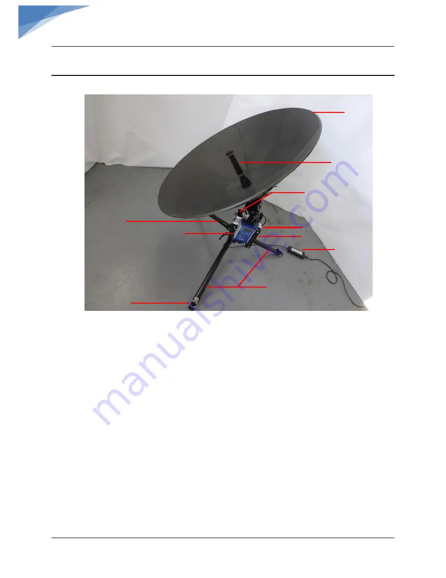
2.  PHYSICAL OUTLINE 


Fig. 2:


iNetVu

®

 MP-80-MOT/100-MOT Front View  


Center Feed 


Tripod Legs 


Reflector 


Tripod Leg 

 DVB 
Module 

Power Supply 


8020 Controller 

Modem (Bracket) 

Modem 

Tie Down Ring 

Summary of Contents for iNetVu MP- 80

Page 1: ...is Man Pack 80cm 100cm User Manual The iNetVu brand and logo are registered trademarks of C COM Satellite Systems Inc Copyright 2020 C COM Satellite Systems Inc 1 877 iNetVu6 www c comsat com Revision...

Page 2: ...C COM Satellite Systems Inc Page 2 of 68 iNetVu MOT 80cm 100cm User Manual 2 This page is intentionally left blank...

Page 3: ...nd logos are registered trademarks of C COM Satellite Systems Inc All other product names mentioned in this manual may be trademarks or registered trademarks of their respective companies and are the...

Page 4: ...OT CLEARANCE 11 6 ASSEMBLY DISASSEMBLY 12 6 1 ASSEMBLY PROCEDURE 12 6 2 DISASSEMBLY PROCEDURE 31 7 POINTING ANTENNA WITH ONBOARD 8020 CONTROLLER 43 7 1 MAIN SCREEN 44 7 2 MENU FEATURES AND SYSTEM CALI...

Page 5: ...ight multi segment carbon fiber ManPack is easy to assemble and points on satellite within minutes The Motorized Manpack systems are complimented by the addition of the onboard 8020 ACU Controller for...

Page 6: ...Page 6 of 68 iNetVu MOT 80cm 100cm User Manual 6 2 PHYSICAL OUTLINE Fig 2 iNetVu MP 80 MOT 100 MOT Front View Center Feed Tripod Legs Reflector Tripod Leg DVB Module Power Supply 8020 Controller Modem...

Page 7: ...MOT 80cm 100cm User Manual 7 Fig 3 iNetVu Motorized MP 80 MOT 100 MOT Back View Ensure to use ballasts or anchors to secure down the antenna failing to do so may result in equipment damage Modem BUC 8...

Page 8: ...zed MP 80 MOT 100 MOT Wiring Diagram DVB Only N C No Connection INPUT 24VDC iNetVu MP 80 RX IN RX OUT iNetVu DVB TUNER N C 8020 IP 192 168 0 3 LAPTOP IP 192 168 0 4 WIRELESS SSID 8020 LAST 3 DIGITS OF...

Page 9: ...h Modem INPUT 24VDC iNetVu MP 80 RX IN RX OUT iNetVu DVB TUNER BUC 8020 IP 192 168 0 2 LAPTOP IP 192 168 0 6 WIRELESS SSID 8020 LAST 3 DIGITS OF SN Be sure all cables including RX and TX are connected...

Page 10: ...C COM Satellite Systems Inc Page 10 of 68 iNetVu MOT 80cm 100cm User Manual 10 5 CLEARANCE REQUIREMENT DWG OUTDATED 5 1 MP 80 MOT CLEARANCE...

Page 11: ...C COM Satellite Systems Inc Page 11 of 68 iNetVu MOT 80cm 100cm User Manual 11 5 2 MP 100 MOT CLEARANCE...

Page 12: ...are identical The only difference is the MP 100 MOT reflector consists of 7 Carbon Fiber segments instead of 5 on the MP 80 MOT 6 1 ASSEMBLY PROCEDURE 1 Set case upright and release lock clips Fig 6 M...

Page 13: ...Ensure the handles are pointing downwards as shown Stabilize tripod using pegs ballasts etc Note Unit must be securely stabilized via ballasts or pegs failing to do so may compromise satellite lock an...

Page 14: ...C COM Satellite Systems Inc Page 14 of 68 iNetVu MOT 80cm 100cm User Manual 14 5 Remove tube 6 Place Turnbuckle on Eyebolt Eyebolt Turnbuckle...

Page 15: ...C COM Satellite Systems Inc Page 15 of 68 iNetVu MOT 80cm 100cm User Manual 15 7 Set Tripod over the Orange Screw and latch Turnbuckle...

Page 16: ...COM Satellite Systems Inc Page 16 of 68 iNetVu MOT 80cm 100cm User Manual 16 8 Use the pegs to secure down the Tripod Legs ensure the pegs are oriented as shown 9 Set the case on its side and open fla...

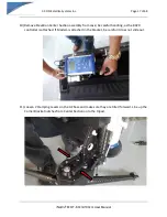
Page 17: ...r Section assembly from case be careful handling as the 8020 controller is attached If Modem is attached in the bracket be careful it does not slide out 11 Loosen 2 Clamping Levers on the AZ base and...

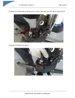
Page 18: ...llite Systems Inc Page 18 of 68 iNetVu MOT 80cm 100cm User Manual 18 12 Make sure the Miniature Clamp Lever is loose to allow the Corner Bracket to slide under it 13 Tighten the Miniature Clamp Miniat...

Page 19: ...80cm 100cm User Manual 19 14 Turn and lock the Clamping Lever by pushing down 15 Connect AZ motor cable from 8020 controller to AZ motor connector note the orientation of the cable connector The clip...

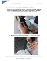
Page 20: ...be tightened to 20 in lbs 5 if torque wrench available Tighten the connector onto the female port Once hand tightened if a torque wrench is not available a good rule of thumb is to wrench tighten the...

Page 21: ...80cm 100cm User Manual 21 c Connect the other end of coax to BUC d Connect cable from DVB Module labelled MODEM to RF IN port on modem e Connect LAN cable f Ensure the coax cables on the DVB module a...

Page 22: ...cm 100cm User Manual 22 a With Power adapter disconnected connect Power cable to Controller Push in to ensure connector snaps in and locks but DO NOT plug the cable into the power source just yet 18 F...

Page 23: ...C COM Satellite Systems Inc Page 23 of 68 iNetVu MOT 80cm 100cm User Manual 23 19 Open the case this top compartment contains the Reflector Petals Feed and Center Hub 20 Remove Center Hub from case...

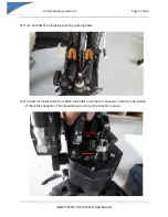
Page 24: ...00cm User Manual 24 21 Install Center Hub and lock into place using the Lock Levers Ensure the Hub plate and EL Mounting Arm Bracket are flush against each other 22 Connect Polarization motor connecto...

Page 25: ...C COM Satellite Systems Inc Page 25 of 68 iNetVu MOT 80cm 100cm User Manual 25 23 Connect external power adapter from 8020 Controller to power outlet 24 Turn on 8020 Controller...

Page 26: ...segments petals Latch 2 segments at a time Do not latch the last 2 segments until all segments have been installed MP 80 will have 5 reflector segments while the MP 100 has 7 reflector segments 26 So...

Page 27: ...Satellite Systems Inc Page 27 of 68 iNetVu MOT 80cm 100cm User Manual 27 27 Lock the latches by rotating the locking mechanism counter clockwise CCW or clockwise CW so the tab is perpendicular to the...

Page 28: ...C COM Satellite Systems Inc Page 28 of 68 iNetVu MOT 80cm 100cm User Manual 28 28 Remove Feed from case and install on hub Turn the Feed clockwise until it locks into place...

Page 29: ...he system was received without an LNB installed It Should be performed only once when the system is first set up or if the hardware is replaced Perform these two routines if replacing and or installin...

Page 30: ...s Inc Page 30 of 68 iNetVu MOT 80cm 100cm User Manual 30 33 Manpack is now setup and ready to use 34 Press FIND SAT button or login to WEB GUI Interface to operate via the WEB see section 6 of this Ma...

Page 31: ...ASSEMBLY PROCEDURE 1 Press Home Stow button on 8020 Controller 2 Power off 8020 Controller once the Homing routine finishes 3 Disconnect RX cable from LNB 4 Disconnect TX cable from BUC 5 Disconnect p...

Page 32: ...ms Inc Page 32 of 68 iNetVu MOT 80cm 100cm User Manual 32 6 Remove Center Feed turn Counter clockwise turn and lift Place in case Place Feed in the case 7 Turn the locking mechanism so the tabs are pa...

Page 33: ...at the top of the dish 9 Remove segments wiggle the center top segment that was un latched so it separates from the rest Once one is removed the rest will easily come apart and place in the case Note...

Page 34: ...C COM Satellite Systems Inc Page 34 of 68 iNetVu MOT 80cm 100cm User Manual 34 10 Disconnect Polarization cable from 8020 Controller...

Page 35: ...C COM Satellite Systems Inc Page 35 of 68 iNetVu MOT 80cm 100cm User Manual 35 11 Release 3 Clamp Levers on Center Hub and remove in the direction of arrows...

Page 36: ...tellite Systems Inc Page 36 of 68 iNetVu MOT 80cm 100cm User Manual 36 12 Rotate OMT with LNB so that the OMT is resting on the hard stop 13 Place Center Hub in the case Align edge so it is straight a...

Page 37: ...C COM Satellite Systems Inc Page 37 of 68 iNetVu MOT 80cm 100cm User Manual 37 14 Close case 15 Turn case on its side and open flap...

Page 38: ...Satellite Systems Inc Page 38 of 68 iNetVu MOT 80cm 100cm User Manual 38 16 Unplug external power cable and put Power Supply in case 17 Remove RF OUT Coax cable from modem and place in case smaller p...

Page 39: ...nc Page 39 of 68 iNetVu MOT 80cm 100cm User Manual 39 18 Disconnect AZ Power cable from AZ gear box Press clip in while disengaging 19 Place attached weather cap on AZ Gear Box connector and release t...

Page 40: ...Satellite Systems Inc Page 40 of 68 iNetVu MOT 80cm 100cm User Manual 40 20 Release AZ EL Clamp Levers and rotate until the Elevation assemble can easily slide out 21 Place Elevation assembly in the...

Page 41: ...tellite Systems Inc Page 41 of 68 iNetVu MOT 80cm 100cm User Manual 41 22 Release Tripod Locking Handles and fold legs The Handles can be locked again after folding the legs to secure them in closed p...

Page 42: ...C COM Satellite Systems Inc Page 42 of 68 iNetVu MOT 80cm 100cm User Manual 42 23 Place Tripod in the case and close flap 24 Close the case and fasten zipper Man Pack is now ready for travel...

Page 43: ...ton functions are described below 1 User Function 1 Used for a variety of functions including Frequency and Demo Mode 2 User Function 2 Used for a variety of functions including Symbol Rate and FTP Mo...

Page 44: ...tems Inc Page 44 of 68 iNetVu MOT 80cm 100cm User Manual 44 7 1 MAIN SCREEN a Status Stat Elevation Angle El Azimuth Angle Az dB signal and Receive Polarity and Angle RX for the selected carrier b Scr...

Page 45: ...r Manual 45 c Scroll Down to Carrier List Press ENTER scroll up and down through the list d Select the Manual Carrier from the list This will enable additional fields Note Only the Manual carrier opti...

Page 46: ...ction select the Satellite Longitude by pressing ENTER button this will allow you to change modify Satellite and RX Polarity Press Enter to continue f Scroll down to DVB Select this screen allows conf...

Page 47: ...C COM Satellite Systems Inc Page 47 of 68 iNetVu MOT 80cm 100cm User Manual 47 7 2 MENU FEATURES AND SYSTEM CALIBRATION 1 Power on 8020 Controller The iNetVu logo will display during bootup...

Page 48: ...angle Azimuth AZ angle and Polarization PL Polarity for the currently configured satellite If the correct satellite is already set press FIND SAT button otherwise continue with steps Note The GPS mus...

Page 49: ...s used or changed Press Enter once highlighted on the screen c Auto PT Enables Disables auto peaking when DVB signal is lost d Info Provides information about the 8020 Controller such as Serial no Sof...

Page 50: ...ct the compass reading to be off or incorrect The system will auto calibrate if it fails to lock on satellite a Press MENU button to access features if not in the MENU b Press ENTER button on the High...

Page 51: ...l and press ENTER This will take RF samples and display a Samples Completed message once finished and display main screen Note Compass Calibration and RF Level should be performed on the system when c...

Page 52: ...atellite GEO list should now be highlighted Press the DOWN or UP arrow to toggle through the list Press ENTER on the desired carrier to select it c In the Carrier List only the Manual Carrier option i...

Page 53: ...ameter Only the RX Polarity is configurable from the front panel and only under MANUAL carrier option e Press ENTER after selecting the desired carrier 7 Press UP arrow to verify and validate that the...

Page 54: ...e carrier is set the press FIND SAT 10 The system will scan determine and set the Polarization angle for the configured satellite and display it on the 8020 Controller screen under RX V or RX H 11 Pre...

Page 55: ...y of manually moving the antenna just to mention a few of the available functions The Web Interface allows the system to be operated via LAN connection accessed through a web browser by entering the c...

Page 56: ...OLS The Web Interface Automatic Controls window allows the user to monitor system operations and perform satellite search FIND SATELLITE as well as stowing homing PREP the system The Configuration and...

Page 57: ...ch routine begins once the search conditions are met i e GPS and RF PREP ANTENNA Re centers the antenna and elevates it to 75 degree position 8 2 2 MANUAL The Manual Controls allow the operator to mov...

Page 58: ...roller and displays it in a browser tab Operator can then save it to the local pc some browsers such as MS Edge will prompt you to either open or save to a file 8 2 4 DEMO This menu option is mainly u...

Page 59: ...anual 59 8 3 CARRIERS Users have the ability to configure ADD CARRIER and save 256 carriers with their Satellite Longitude Frequency Symbol Rate and other configurable parameters Each Carrier can have...

Page 60: ...ging carrier will automatically overwrite the MANUAL carrier with the selected carrier information 2 CARRIER NAME The name of the carrier that will be displayed on the 8020 LCD 3 SATELLITE LONGITUDE O...

Page 61: ...power the LNB from the controller or if the user would like to find satellite without the use of a modem This option allows for power from the controller to be supplied to the LNB through the RX IN c...

Page 62: ...R button After filling out all the required fields parameters click on the SAVE TO CONTROLLER button to add the carrier to the carrier list DELETE CARRIER Removes Carrier from Carrier s list DOWNLOAD...

Page 63: ...w allows the user operator to configure search parameters The operator can enable the compass to calibrate automatically configure the satellite Search Method Controller IP address etc and as well ove...

Page 64: ...PENAMIP PORT The port that the modem uses to establish communication with the 8020 Controller This field becomes configurable once OPENAMIP Search Method is enabled Field disabled in DVB ONLY search m...

Page 65: ...e iNetVu system OVERRIDE mode only 8 4 3 NETWORK INTERFACE WEB FTP INTERFACE WIFI and WIRED are the two options Setting the interface to WIFI enables the wireless communication interface default 8020...

Page 66: ...0 controller AUTO IP The iNetVu 8020 Controller could obtain a dynamic IP address from a DHCP Server i e router modem etc CONTROLLER IP ADDRESS The IP address assigned to the iNetVu 8020 Controller SU...

Page 67: ...ellite Systems Inc Page 67 of 68 iNetVu MOT 80cm 100cm User Manual 67 8 5 ABOUT Displays information to the user such as the 8020 Software version Serial number MAC Address and the current Satellite L...

Page 68: ...2017 ITE Class A Manufacturers Name C COM Satellite Systems Inc Manufacturers Address 2574 Sheffield Road Ottawa Canada K1B 3V7 Importers Name optional Importers Address optional Type of Equipment iNe...

Reviews: