PN 060914-000
Revision C, October 2001
Page 1-2
© 2001, C-COR.net Corporation
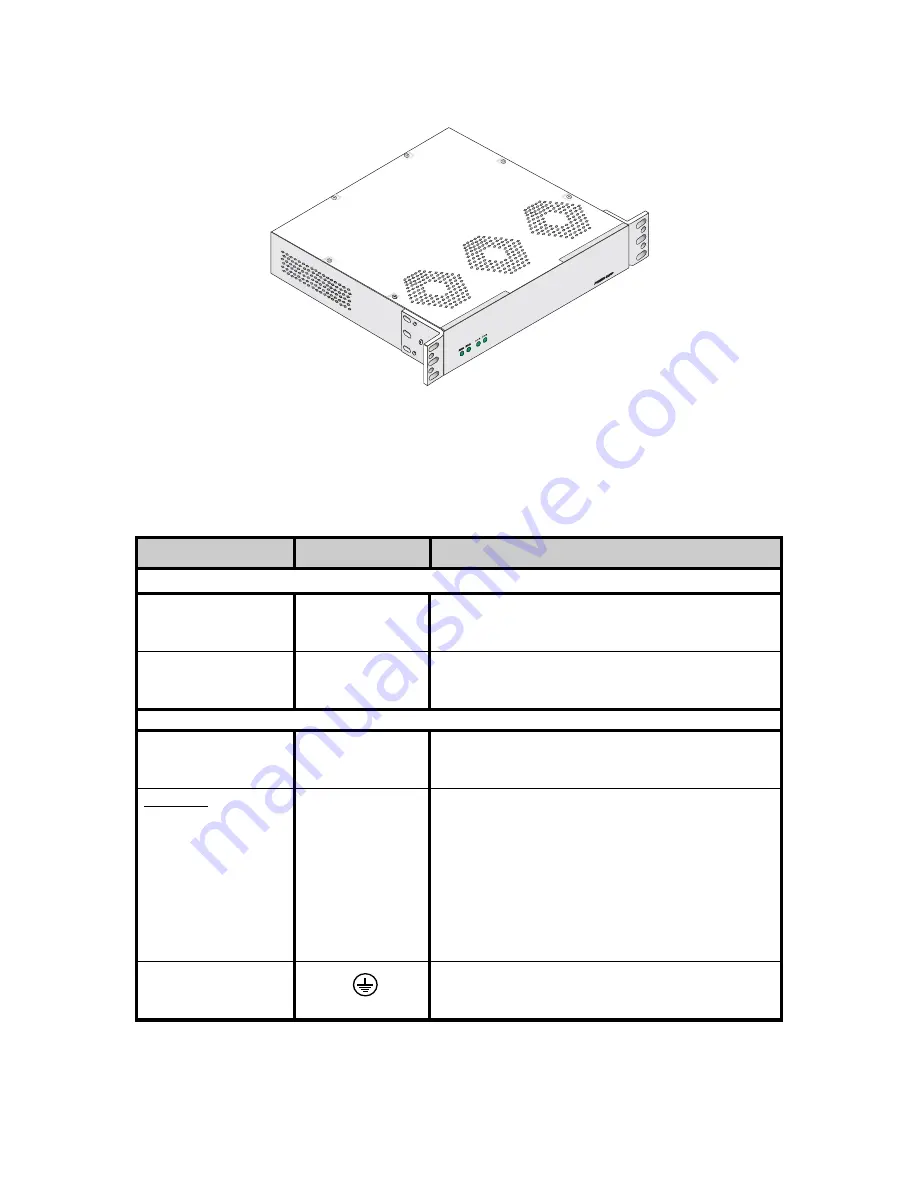
Figure 1-1. Integrated Fan/Power Supply Assembly
2
.03
AC input and DC output(s) are located on the rear of the assembly. The AC and DC LED
indicators are located on the front panel of the assembly. Table 1-1 describes the front and rear
panel features of the Integrated Fan/Power Supply assembly.
Table 1-1. Integrated Fan/Power Supply Front and Rear Panel Features
TYPE
NOMENCLATURE
FUNCTION
Front Panel Features
LED
AC-
Green when AC (-A and/or -B) input is normal:
(green)
110 VAC version:
90 - 130 VAC
220 VAC version:
180 - 246 VAC
LED
DC-
Green when DC (-A and/or -B) output is normal:
(green)
-48 VDC ±5%
Rear Panel Features
AC Input
AC power switch, EMI line filter, 2 AC fuses, and
Power Module
IEC compatible line cord receptacle (separate line
cord included)
DC output
Terminal Block A
Power Supply A
Individual
3-position
screw terminals:
- 48V
-V,-48 VDC Line
+V, -48 VDC Return
GND, Office ground
Terminal Block B
Power Supply B
Individual
3-position
screw terminals:
(Dual Version only)
- 48V
-V, -48 VDC Line
+V, -48 VDC Return
GND, Office ground
Ground Post
Spring-loaded ground post that connects to
Office ground
Summary of Contents for Optiworx HW Series
Page 1: ...IntegratedFan PowerSupply Procedures Manual 060914 000 Rev C...
Page 2: ......
Page 10: ...x FRONT MATTER 060914 000 Rev C This page deliberately blank...
Page 35: ......


