PN 060914-000
Revision C, October 2001
Page 2-18
© 2001, C-COR.net Corporation
AC Input Failure
(continued)
DLP-503
Page 5 of 6
Module LED
Table 503-1
(continued)
Indications
Fan/Power Supply Fault Diagnostic/Probable Cause
b.
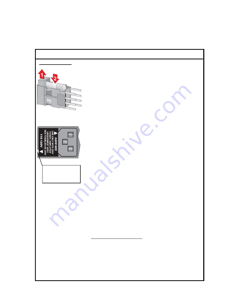
To replace the fuses back
into the fuse holder:
1. Lift fuse holder safety compartment so that the fuse can be
placed on the fuse clips.
2. Place the fuse on front (under safety compartment) and back
fuse clips, then snap-down into place. The safety
compartments will drop down into the body of the fuse
holder assembly. Repeat 9b. if the second fuse requires
replacement.
10.
To replace the fuse holder
back into the Fan/Power Supply AC input
power module:
a. Making sure to observe proper insertion position (based on
input AC voltage), slide fuse holder assembly back into the power
entry module:
For 115 VAC (Models HW-PSFAN-x-110), rotate the fuse
holder until the 110-120V triangular symbol on the top of
the fuse holder is pointing to the white line located at the
bottom-left side of the AC input power module (as shown
in the illustration).
For 220 VAC (Model HW-PSFAN-1-220), rotate the fuse
holder until the 220-240V triangular symbol on the top of
the fuse holder is pointing to the white line located at the
bottom-left side of the AC input power module.
b. Snap the fuse holder assembly back into the AC input power
module. Return to the step that initiated this action.
DC-A Power Supply Failure
11. The primary power supply (DC-A), which provides the power to all the front panel
LEDs, has failed. Reconnect the power cord to the Fan/Power Supply assembly and
insert the male plug into the AC outlet. Set the power rocker switch to the
I
(on) position. On the rear panel of the Fan/Power Supply assembly, using the digital
voltmeter (observing the marked polarity) check that a supply voltage of -40 to -56.7 VDC
is present at the DC output terminals (POWER SUPPLY A - 48V and B if a dual
supply version).
White power rating
indicator line located
on the
Power Entry Module
Summary of Contents for Optiworx HW Series
Page 1: ...IntegratedFan PowerSupply Procedures Manual 060914 000 Rev C...
Page 2: ......
Page 10: ...x FRONT MATTER 060914 000 Rev C This page deliberately blank...
Page 35: ......


