21/08/2019
6
5
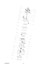
Assembly Instructions
Place Stand with triangular base on a work surface with wide end towards user.
Place Back Frame (plastic block, not the metal Back Plate) O-Ring groove side down
onto inner notch on Stand.
Carefully fit Electrode Gasket into recess of Back Frame and then fit Electrode,
ensuring that the Electrode Gasket stays in place. Current Collector, Insulating Disc,
Insulating Sleeve.
Place Back Plate over the Back Frame, feet towards user, threaded rods passing
through the Back Frame. Screw Electrode Pressure Knob into Back Plate, knurled ring
to rear of Back Plate, until it just touches the Electrode Assembly.
Pick up the whole sub-assembly, turn it over, place it on the Stand. Fit O-Ring (note
that the O-Ring grooves on the two Frames are of different sizes, with O-Rings to
match, so take care to match the two O-rings to the grooves.
Optional - Fit Membrane Gasket, Membrane and second Membrane Gasket. The
purpose of the Membrane Gaskets is to locate a Membrane, if used.
Fit O-Ring into face of Front Frame and fit the Front Frame over the threaded rods.
Fit the Electrode Gasket into recess and fit the Electrode ensuring that the Electrode
Gasket stays in place
Place brass Current Collector onto Electrode. Fit Insulating Disc and Insulating Sleeve
onto the Current Collector.
Place Front Plate over the threaded rods.
Fit Electrode Pressure Knob. Loose fit only – knob just touching collector
Fit Insulating Disc, then Washers, then Terminal Knob.
Fit four Thumb Nuts loosely – do not tighten fully
Take the unit off the stand and rest it on its feet to ensure that frames are aligned
Tighten the four corner Thumb Nuts, bit by bit, opposite corners together.
Finally tighten the two Electrode Pressure Knobs
Fit Electrode Ports and Reference Electrode Ports as required. Use Teflon tape for a
good seal. If reference electrodes are not used then fit Reference Electrode Port Plugs.
The cell is now complete.


