CM2 Sidescan Sonar User Manual
12. Repair and Replacement
Whenever the rear bulkhead (or the nose) has been removed the end of the tube is vulnerable to damage.
Even a short drop on to a hard surface may distort the bore.
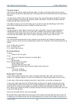
To remove the PCB, first disconnect all attached connectors. Then remove the M4 screw in the rear
bulkhead bracket that retains the PCB. For later units an M4 stud and locknut is used instead of an M4
screw. When removing or re-attaching the PCB be careful not to damage the small thermometer chip on the
underside of the PCB by catching it against the bracket.
Reassembly requires care. The two O-ring seals on the rear bulkhead may be renewed using standard nitrile
rubber seals of 49.5mm inside diameter, section diameter 3.0mm, medium hardness (Shore Hardness A70).
All the sealing surfaces must of course be clean and dry, and they should be very lightly lubricated with the
silicone grease provided The replacement of the rear bulkhead O-rings, and cleaning, are best done with the
PCB removed.
Reassemble the tube assembly to the keel/transducer assembly by the reverse process. Rotate the
transducers to the 10º depression angle (cam dots high) then remove both cable ties from the slots.
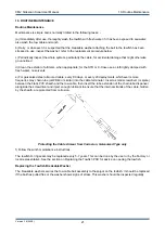
There is normally no need remove the nose of the towfish but, if there is, proceed as follows. Screw the two
locking screws inwards (clockwise, lightly) to the full extent. This will release the nose but it will be retained
by the grip of the O-rings. Rotate the nose to loosen this grip, pulling outwards at the same time. If necessary
use two screwdrivers, with their blades in the recesses each side of the nose, to start the extraction process.
Putting a rubber band round the nose may enable it to be gripped more easily.
As the nose is replaced, rotate it to align the locking screws. Wind each screw counter-clockwise just
enough to lock the nose in position. Use MINIMUM torque.
Replacing a Transducer
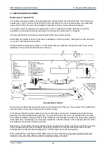
To replace one or both of the acoustic transducers, do not separate the rear bulkhead from the towfish tube.
Remove the tube assembly as described in the previous section. Remove the two temporary cable ties and
then lift out the pair of transducers, still hinged together with the hinge rod. Slide out the hinge rod.
Be careful to retain the adjuster components on the rod. They must be grouped at the front (screw) end, with
the screw head on the cam pointing forwards. The assembly order on the rod is the adjuster components
(cam, coil spring, M5 washer) then the transducers..
Never remove the angled backplates from the transducers.
Replace the transducers by the reverse procedure, and refit the tube assembly as described earlier.
Repairing the Tow Cable
In the event that the “wet” end of the cable requires re-termination, this may be performed by the Factory.
Alternatively the cable may be re-terminated in the field using the termination kit, available as a standard
accessory. Steel-armoured cables cannot normally be repaired mid-way along their length by splicing
because the bulk of such a splice would prevent the cable from layering properly. Manually handled “soft”
tow cables can, in an emergency, be spliced but it is difficult to ensure that the splice retains sufficient
strength and such a repair is not recommended.
If a steel-armoured cable is damaged close to the winch end and the damage is such that the cable is
unserviceable, then this damaged inboard section will need to be cut out. The shortened cable will then need
to be re-terminated on to the winch. In these circumstances, or if the cable is to be completely replaced,
consult Section 16 or 17 for guidance on removing and replacing a tow cable on the CM2-WIN-300 or SK172
winches. The guidance for these winches may also be applied, where appropriate, to larger winches.
Replacing the Safety Lanyard
A damaged or worn lanyard should be replaced with a factory-produced item to ensure that the dimensions
are correct.
The latest design of lanyard is superior to the earlier pattern and is easier to retrofit.
Version 3.6 (2008)
24


