MOUNTING Page
13
4.1.5
Cabling
Use the cables included, one for power supply and one signal cable for
connecting the display to the R4 Navigation Sensor, external systems and
sensors. Note that the signal cable requires a minimum bending radius of 10
cm.
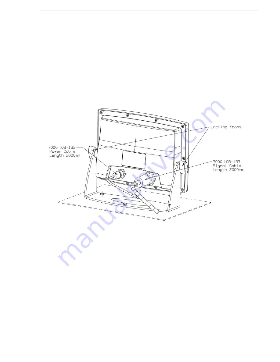
Connect the R4 Display Power Cable, marked “7000 108-132”, and the R4
Display Signal Cable, marked “7000 108-133”, to the corresponding
ConXall connectors on the back of the R4 Display. See Figure 4-9 below
(illustrating a gimbal mounted R4 Display).
Wire the open end of the cables as described in section 5.2 and Appendix
[A.8].
Figure 4-9: Connecting the power cable and the signal cable to the R4 Display
Note: The Signal cable for connecting to the R4 Display and the Power and
Data cable for connecting to the R4 Navigation Sensor both use 18 pin
connectors. Make sure they are not interchanged! The R4 Display Signal
cable is marked with “7000 108-133” and can also be identified by the fact
that only 13 pins are mounted in the male connector.
4.1.6
Power Supply
The R4 Display can be connected to an emergency power source. If
connected to an emergency battery, a re-calculation must be made for the
battery capacity. For power consumption, see section 8.1.
The R4 Display is designed to operate on 24 VDC. The nominal power used
is 8.5 W. The R4 Display shall be externally fused (slow blow fuse) with a
2 A fuse.
Install according to section 5.2 and Appendix [A.8].
Summary of Contents for 1000 R4
Page 18: ...MOUNTING Page 12 Figure 4 7 Panel mounting R4 Display Figure 4 8 R4 Display panel mounted ...
Page 79: ...TECHNICAL SPECIFICATIONS Page 11 ...
Page 80: ...TECHNICAL SPECIFICATIONS Page 12 APPENDIX A J4N SCHEMATIC ...
Page 81: ...TECHNICAL SPECIFICATIONS Page 13 APPENDIX B J4N PCA LAYOUT ...


