APPENDICES Page
53
APPENDIX A.5 – FRONT PLUG PORT CHARACTERISTICS
The Front Plug port is available on the front of the R4 Display. In a R4
Navigation System the port is not used. It is up to the user to use this port
for own purposes if desired. In a R4 AIS Transponder System, this port is
used to connect to the Pilot port on a R4 Transponder.
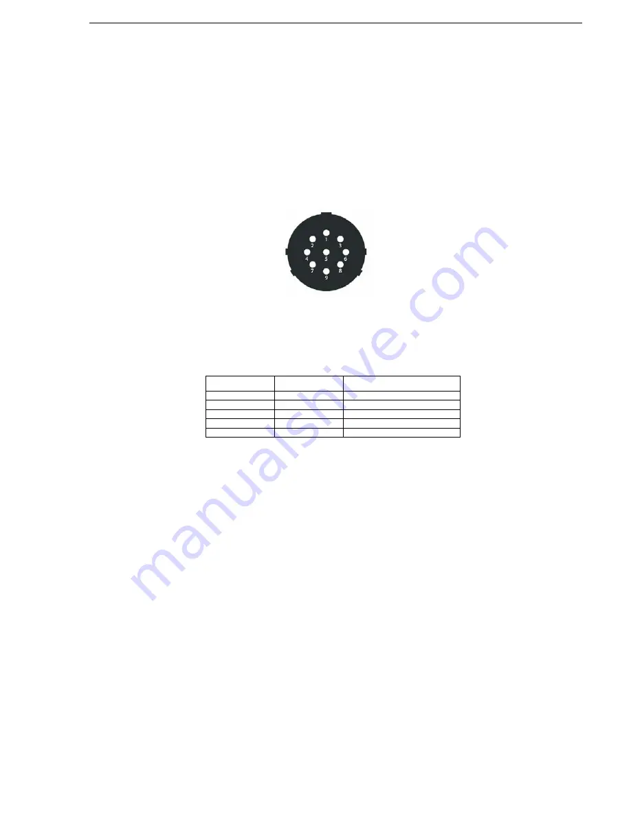
The connections of the front plug port are directly forwarded to the 9-pin
connector plug available on the front of the R4 Display. The pin numbering
of the front plug is described in the figure below.
Front plug pin numbering
The connections between the signal cable and the front plug are listed in
following table.
Internal Signal to Front plug connections in the R4 Display
Front plug
Signal plug
Color in signal cable
PIN 9
PIN 12
Shield
PIN 1
PIN 13
Violet
PIN 5
PIN 15
Red/blue
PIN 4
PIN 16
Black
PIN 6
PIN 18
Gray/pink
Summary of Contents for 1000 R4
Page 18: ...MOUNTING Page 12 Figure 4 7 Panel mounting R4 Display Figure 4 8 R4 Display panel mounted ...
Page 79: ...TECHNICAL SPECIFICATIONS Page 11 ...
Page 80: ...TECHNICAL SPECIFICATIONS Page 12 APPENDIX A J4N SCHEMATIC ...
Page 81: ...TECHNICAL SPECIFICATIONS Page 13 APPENDIX B J4N PCA LAYOUT ...


