background image

Maintenance

Handling

- The C.Scope Cable Avoidance Tool and Signal Generator are rugged instruments designed for the rigours of

every day use. However, to ensure that the specified accuracy is maintained, it is essential to treat the instruments with
care by avoiding shocks, vibration and excesses of temperature.

The construction of the C.Scope Cable Avoidance Tool and Signal Generator incorporate weather proof seals, however,
they are not guaranteed to prevent water ingress if the units are immersed.

Cleaning

- If required the equipment can be cleaned with a sponge dampened with warm water. A mild soap may be used

if required. The use of solvents should be avoided.

Do not allow moisture in the battery compartments or near the connectors.

Storage

- The equipment should be stored in a clean, dry place. The temperature should not exceed the range -10˚C to

+50˚C. If stored for long periods the batteries should be removed.

37

Summary of Contents for XD

Page 1: ...Instruction Manual Cable Avoidance Tool Cable Avoidance Tool XD Signal Generator SG A Signal Generator SG V CABLE AVOIDANCE TOOLS...

Page 2: ...conditions such as hills and mountains can effectively screen radio signals and prevent a detectable ground current The C Scope Cable Avoidance Tool alone will not always locate every conductor so al...

Page 3: ...inting 10 Tracing 11 Using the Signal Generator 12 Batteries 13 Direct connection 14 Street lighting 16 Signal Clamp Injector 17 Searching 18 Tracing 19 Induction 20 Searching 21 Multiple Services 23...

Page 4: ...ch Sensitivity control 3 position mode switch Battery compartment Replaceable wear foot The C Scope Cable Avoidance Tool And XD Model Digital display Mode selected Generator Power Radio showing freque...

Page 5: ...h Batteries Direct connection socket Auxiliary earth lead socket Accessory tray The C Scope Signal Generator SG A and SG V Models Digital display SG V only Battery condition indicator Mute loud settin...

Page 6: ...The C Scope Signal Generator SG A and SG V Models Accessory tray Accessory tray holding clips Earth stake Direct connection leads Crocodile clips Auxiliary 10m earth lead Connection magnet 3...

Page 7: ...wer signal is created Supplies to buildings or plant using very little or no electricity will not have a detectable power signal Pot ended or capped cables These will never have any current flowing th...

Page 8: ...o determine WHAT the service is in Radio mode only it s position Radio signals do not favour one utility over another The depth of the buried service CANNOT be judged by the strength of the radio sign...

Page 9: ...Direct Connection The Signal Generator is attached directly to the service using either the Direct Connection Leads or one of the accessories available for use with the Signal Generator such as the Si...

Page 10: ...Locator Batteries Push the two clips back to release the battery compartment door Remove ALL EIGHT used batteries and replace with new ones Be careful to insert the new batteries the correct way round...

Page 11: ...R swing the locator such that it moves away from the vertical Your middle or little finger should be used to squeeze and hold on the On Off trigger Your index finger will then be free to adjust the se...

Page 12: ...lk slowly and keep the locator upright at all times and stationary by your side 5 As you approach the area in which there is a signal the locator will emit an audible response and show a visual respon...

Page 13: ...the sensitivity is reduced enough then a clear peak response will be seen on the bar display as the locator traverses the service The locator is positioned directly above the buried service when the b...

Page 14: ...depth of the service a T connection or the end of the service Finding Lost Signals 1 Locate in a circle at least 1metre around the point where the signal was lost This should locate the service if it...

Page 15: ...he route of that service Signal Clamp The Signal Clamp is an accessory that allows the Signal Generator signal to be applied to a specific cable without having to make electrical contact with that cab...

Page 16: ...of the indicator filled in then the batteries will need to be renewed before locating work can begin Changing the Batteries Remove the accessory tray Undo the two round knurled retaining screws situat...

Page 17: ...to the pipe at your point of access using the crocodile clip Ensure that you have a secure and clean grip on the pipe with the crocodile clip 3 Turn the Signal Generator on WARNING Never connect direc...

Page 18: ...e better the signal will be on the metal pipe If there is no change of tone at all it may be that some dirt rust or paint on the pipe is preventing the direct connection lead from making a good contac...

Page 19: ...les as for connecting the Signal Generator to a metal pipe except attach the red direct connection lead to the OUTSIDE of the lamp column WARNING NEVER open the lamp column door to gain access to the...

Page 20: ...doned cables that have been cut off where they appear above ground or small cables supplying unearthed equipment WARNING DO NOT use the Signal Injector on systems with voltages in excess of 240 volts...

Page 21: ...nal Generator 2 Adjust the Sensitivity so that the locator is just showing a visual response and emitting an audible response 3 If possible walk in a COMPLETE circle around the connection point trying...

Page 22: ...tracing technique used on Power or Radio Modes but with the following differences The signal that the locator is detecting will get weaker the further away from the Signal Generator that you go It wil...

Page 23: ...ally to Induction Mode when the socket is clear 2 Place the Signal Generator UPRIGHT on the ground where you suspect there may be some services buried Make sure the Signal Generator is IN LINE with th...

Page 24: ...up the airborne signal rather than the signal induced onto the buried service 2 Stand so that you are roughly in line with the end of the Signal Generator and hold the locator so that the side of the...

Page 25: ...trength of the induced signal on the buried service by improving the positioning of the Signal Generator Once the buried service has been pinpointed then by moving the position of the Signal Generator...

Page 26: ...of the Signal generator but NOT directly below Limitations of Induction Method There are limitations concerning what can be achieved when using a Signal Generator on the Induction mode compared to the...

Page 27: ...end on whilst you hold the locator 3 Adjust the Sensitivity so that the locator is just showing a visual response and emitting an audible response 4 In unison slowly walk across the site staying the...

Page 28: ...ointed by using the Locator switched to Generator mode The Sonde can be used in pipes as small as 50mm in diameter and up to 5 metres deep It will NOT transmit a signal through a metal pipe The Sonde...

Page 29: ...inting Before inserting the Sonde into the pipe itself it is best to set up the locator such that the Sensitivity is already correctly adjusted to suit the pipe depth 1 The blade of the locator must b...

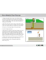
Page 30: ...position of the Sonde The locator is now set up ready for tracing the Sonde 5 Push the Sonde up the pipe 6 With the locator turned on walk from the pipe access point in the direction that the Sonde w...

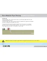
Page 31: ...al Generator signal is applied using the Direct Connection to a metal pipe method as shown in Using the Signal Generator Only one lead is connected to the Plastic pipe tracer the other is connected to...

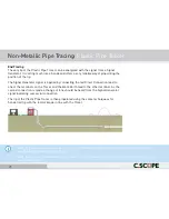
Page 32: ...th the signal from a Signal Generator It is acting much like a Sonde and offers a very reliable way of pinpointing the position of the tip The Signal Generator signal is applied by connecting the red...

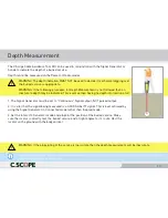
Page 33: ...sition of the buried service Make sure the locator is directly over the buried service and at right angles to it s route Rest the locator on the ground with the body vertical WARNING The depth indicat...

Page 34: ...ges in depth Near to a T junction in the service At the very end point of a service At any point where the signal has coupled onto an adjacent service Close to any large metallic objects such as metal...

Page 35: ...ror codes when a depth measurement has been attempted 1 The service is too shallow less than 0 20m deep for the Locator to obtain an accurate depth It should be possible to calculate the depth by rais...

Page 36: ...ol at a fluorescent light from a distance of 1m Switch the light on A loud tone should be heard and the display should read greater than 50 full scale Reducing the sensitivity should cause the display...

Page 37: ...duced Place the Signal Generator on the ground in the normal orientation and switch on a tone should be heard Set to Continuous and ensure highest output power is selected With the C Scope Cable Avoid...

Page 38: ...nged to create an open loop on the ground of approximately 1m diameter Check that a signal can be detected by the Cable Avoidance Tool in Generator Mode when pointed closely at the loop Depth Measurem...

Page 39: ...e Signal Generator The Signal Generator is turned on with lowest power and continuous mode selected The C Scope Cable Avoidance Tool should then be held vertically above the longer wire approximately...

Page 40: ...Tool and Signal Generator incorporate weather proof seals however they are not guaranteed to prevent water ingress if the units are immersed Cleaning If required the equipment can be cleaned with a sp...

Page 41: ...uracy 10 of depth Depth Measurement XD Only G Mode only Range 0 2m to 3m line 0 85m to 4 5m sonde Accuracy 5 1m Construction Case moulded from high impact plastic sealed to IP65 Weight 2 9kg including...

Page 42: ...aximum short circuit output current 18mA rms Maximum power 320mW into 1k load Connection mode is automatically selected when lead is plugged into socket Induction Mode Maximum field strength at 10m 40...

Page 43: ...e the next service is due is marked on the equipment Repairs Before returning equipment suspected of being faulty please check the machine carefully with a fresh set of batteries Check the battery con...

Page 44: ...C Scope International Ltd Kingsnorth Technology Park Wotton Road Ashford Kent TN23 6LN t 01233 629181 f 01233 645897 e info cscope co uk w www cscope co uk Part no B1069 01 05...

Reviews: