background image

User's Manual

HS-6500

ELECTROMAGNETIC INTERFERENCE
AND WARNINGS

3

CAUTION: It is very important that you read this information regarding the possible

effects of Electromagnetic Interference on your power chair.

Powered wheelchairs and motorized scooters may be susceptible to electromagnetic

interference (EMI), which is interfering electromagnetic energy (EM) emitted from sources

such as radio stations, TV stations, amateur radio (HAM) transmitters, two-way radios,

and cellular phones.  The interference (from radio wave sources) can cause the power

chair to release its brakes, move by itself, or move in unintended directions.  It can also

permanently damage the power chair control system. The intensity of the interfering

EM energy can be measured in volts per meter (V/m).  Each power chair can resist EMI

up to a certain intensity. This is called its "immunity level." The higher the immunity level,

the greater the protection will be. At this time, current technology is capable of achieving

at least a 20 V/m immunity level, which would provide useful protection from the more

common sources of radiated EMI. The immunity level of this product is 20 V/m.

There are a number of sources of relatively intense electromagnetic fields in the everyday

environment.  Some of these sources are obvious and easy to avoid. Others are not

apparent and exposure is unavoidable.  However, we believe that by following the warnings

listed below, your risk to EMI will be minimized.

Some cellular telephones and similar devices transmit signals while

they are ON, even when not being used.

Electromagnetic Interference and Warnings

The sources of radiated EMI can be broadly classified into three types:

1.Hand-held portable transceivers (transmitters-receivers) with the antenna mounted

directly on the transmitting unit.  Examples include: citizens band (CB) radios,

"walkie talkie," security, fire, and police transceivers, cellular telephones, and other

   personal communication devices.

2.Medium-range mobile transceivers, such as those used in police cars, fire trucks,

ambulances, and taxis. These usually have the antenna mounted on the outside of

the vehicle.

Summary of Contents for HS-6500

Page 1: ...HS 6500 User s Manual C T M PowerChair C T M PowerChair C T M PowerChair Multi Adj Fix Frame...

Page 2: ...netic Interference and Warnings 3 Safety Instructions 5 Initial Overview 6 Operation 7 Disassembling 16 Safe Driving Techniques 18 Batteries and Charging 20 Tire 21 Maintenance and Cleaning 22 Trouble...

Page 3: ...ur new chair so that you comprehend the technical advantages of HS 6500 All assembly and maintenance should be performed after you fully understand the content of this manual to avoid any hazard or da...

Page 4: ...513 BH The Hague The Netherlands We wish you an enjoyable riding experience If you have any questions you can contact CHIEN TI ENTERPRISE CO LTD No 13 Lane 227 Fu Ying Rd Hsin Chuang Taipei Taiwan Tel...

Page 5: ...s capable of achieving at least a 20 V m immunity level which would provide useful protection from the more common sources of radiated EMI The immunity level of this product is 20 V m There are a numb...

Page 6: ...ces such as radio and TV stations amateur radio HAM transmitters two way radios and cellular phones can affect the power chair Following the warnings listed below should reduce the chance of unintende...

Page 7: ...e sure of your own ability and your limitations in terms of strength and endurance Please be aware that any adjustments on the power chair may affect the handling and performance 5 Before attempting a...

Page 8: ...urself with the controls and how they operate Controller Bracket Adjustment Knob Handlebar Height Adjustable Armrests Armrest Disassemble Knob Super Responsive Digital Joystick Controller Footrest Fix...

Page 9: ...s Move power chair forwards Backwards Move power chair backwards Left Move power chair left Right Move power chair right Controller Position Adjustment By release Controller Bracket Adjustment Knob to...

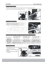
Page 10: ...s below Comparison Seat Depth Adjustment Seat Incline Adjustment Footrest Adjustment 1st 2nd 16 Standard 1st hole Standard 2nd 3rd hole Forbidden 1st 2nd hole 2nd 3rd 17 Standard 2nd hole Forbidden 1s...

Page 11: ...e 11 Figure 11 L M N N1 O1 O2 front rear 1 2 3 4 1 2 3 4 5 Footrest Adjustment 1 Take off two Footrest Fixation Screws M 2 Adjust to required hole s position aim at hole s position and tighten screws...

Page 12: ...eight Adjustment 1 Take off both side s height fixation screws P 2 Adjust to required position 3 Aim for the required hole s position to tighten height fixation screw Careful not to interfere with fro...

Page 13: ...ed position 4 Aim two knobs V at hole s position then tighten 1 Take off backrest pad as illustration by release it s vel cro See Fig 19 2 Release all backrest s vel cro straps See Fig 20 3 Release an...

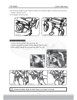
Page 14: ...th two screws See Fig 25 3 Assemble climber as arrows indicate by aim it to both side s holder See Fig 26 5 Adjust support brace to a comfortable position and reassemble by aiming for the holes then v...

Page 15: ...for both sides by repeat 1 3 steps 1 Screw must aim at the hole See Fig 30 2 Tighten two bolts no bolts if with climber See Fig 31 3 Using tool to tighten screws and bolts See Fig 32 4 According to dr...

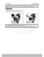
Page 16: ...33 Figure 33 Figure 36 Figure 36 Figure 35 Figure 35 Figure 34 Figure 34 Figure 37 Figure 37 Figure 38 Figure 38 Knob Figure 39 Figure 39 Battery terminal A Battery terminal A Lighting controller ter...

Page 17: ...User s Manual HS 6500 11A 11B 15 11 Coordinate and fix cables by using 8 cord clips See Fig 41 42 Figure 41 Figure 41 Figure 42 Figure 42 Cord Clip Cord Clip...

Page 18: ...e off Figure 43 Figure 43 W W1 DISASSEMBLING 16 Disassemble Armrest 1 By releasing knob X 2 For the armrest with controller you have to detach controller s wire harness X1 and clip X2 first to disasse...

Page 19: ...with same power fuse is required Battery connectors must be disconnected before replacing fuse Z4 17 Fuse Replacement 1 Disassemble batteries according to steps 1 4 2 Open fuse box A3 remove fuse A4 3...

Page 20: ...clean from sand and salt water Indoor Outdoor Driving When driving indoors keep the speed to a minimum to avoid the risk of collision For outdoor driving be cautious of wet surfaces loose sand large c...

Page 21: ...rives the wheelchair slowly up or down the ramp ensuring that the chair is driven in the centre of the ramp tracks If possible have an assistant monitor the chairs progress and prevent tipping of the...

Page 22: ...e front of the controller 3 Connect the battery charger to a standard wall power outlet 4 Switch the power on During the recharge 1 While the batteries are being recharged a red light will appear on t...

Page 23: ...M dealer Front wheels 8 air tires Rear wheels 13 air tires Follow these easy steps to replace the tire 1 Use an ratchet and socket to remove the drive wheel screw from the centre hub of the wheel See...

Page 24: ...pet fibres 8 Lightly oil axle pin wheel axles and bearings once every three months if necessary 9 Inspect the tires Tread depth should not be allowed to drop below 1 16 10 Use only recommended batteri...

Page 25: ...on the type of wheelchair you have one possibility is the battery charger is connected The parking brakes have a bad connection Check the parking brake and motor connections Make sure the control sys...

Page 26: ...vice versa the steps 5 If none of these suggestions correct the problem contact your authorized dealer If charging your power chair over 14 hours and the light on the charger does not change to green...

Page 27: ...ive Train Battery Weight Motor Size Travel Range Battery Charger Electronics Seat Type 1040 mm 41 580 mm 23 920 mm 36 200 mm 8 N A 320 mm 13 74 kg 163 lbs 8 kmph 5 mph 136 kg 300 lbs 100 mm 4 8 degree...

Reviews: