QT601-2 Quantec Controller
General Note
Quantec systems should be installed using Network Splitters. These pre-commissioning instructions are based on their use for the
following reasons:
• They ensure voltage drop problems are substantially avoided.
• They blow a fuse and keep most of the system working if a network limb is shorted.
• They allow cable and equipment faults to be easily found and isolated.
• They allow the system to be connected a section at a time, avoiding problems with other trades initialising devices out of sequence.
Using other wiring schemes may work, but installation errors will be more difficult to detect and voltage drop may be a problem.
Do not megger the wiring with ANY devices connected.
Pre-Commissioning
The installing contractor should carry out the following tests so that the commissioning engineer can get the system operating
quickly. If these are not done, commissioning may be refused or extra charges made.
Things you will need:
Quantec Main instructions (this document) available from your Installer or C-TEC
; Individual instructions supplied with each
device
; Terminal screwdriver
; 5 mm flat blade screwdriver
; 3 mm Allen key
; Side cutters
; Wire strippers
; Digital
multimeter
.
Things you will be expected to have done:
1. All spine wiring from the Quantec Controller to the network splitters should be in place, checked & certified correct.
2. All limb wiring from the network splitters to network devices should be in place, checked & certified correct.
3. The spine and limb cables should be left connected to the splitters.
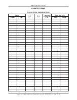
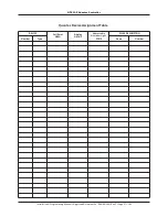
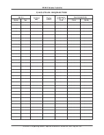
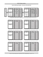
4. All limb wiring should be labelled so you know which devices are connected to where. Use the Splitter Connection Chart
(located at the back of this document).
5. All room wiring to ceiling pulls, overdoor lights and slave call points (if fitted) should be in place, checked & certified correct.
Checking the Spine Wiring
• Power up the Quantec Controller. A number of messages will flash quickly on the Controller’s LCD display before the
words ‘QUANTEC’ and the time in hours and minutes appear constantly (please note, the time shown may not be correct).
• Do not connect batteries. Look at the green power lights on the network splitters.
• If none are lit, check the spine voltage at the Quantec Controller – you should see a changing reading in the range of 16 to
17 volts DC. If the voltage is much lower, disconnect the spine and check the voltage again. If the reading jumps up, you
have a wiring fault. If you fix this fault and the reading still remains low, you may have another wiring fault. If you suspect
the Quantec Controller may be faulty, disconnect the spine wiring at the Controller and check the voltage at the Quantec
Controller with no wires connected. If the voltage is okay (i.e. within the range 16 to 17 volts DC) you still have wiring faults.
• A short on the spine will not blow a fuse but nothing will work except the display on the Quantec Controller.
• If any one splitter is not lit, it is probably not connected or the wiring to it is shorted.
• Sort out any wiring problems and repeat the tests until all green lights are lit on the splitters.
Checking the Limb Wiring
• Go to a network splitter and connect one limb at a time, carrying out the following tests.
• If any fault lights are lit, check the fuses at that splitter. The limb connected to a blown fuse is probably short circuit. Fix
the fault and replace the fuse (always fit 400 mA 20 mm quick blow fuses). Note that, if the limb wires are very long, it is
possible that a short will not blow a fuse. However, the fault can be found by disconnecting limbs in turn (when the short
circuit limb is disconnected the network should spring into life).
Appendix 7 - Pre-Commissioning Instructions
Installation & Programming Manual • Approved Document No. DNU6012001 Rev 5 • Page 32 of 42


