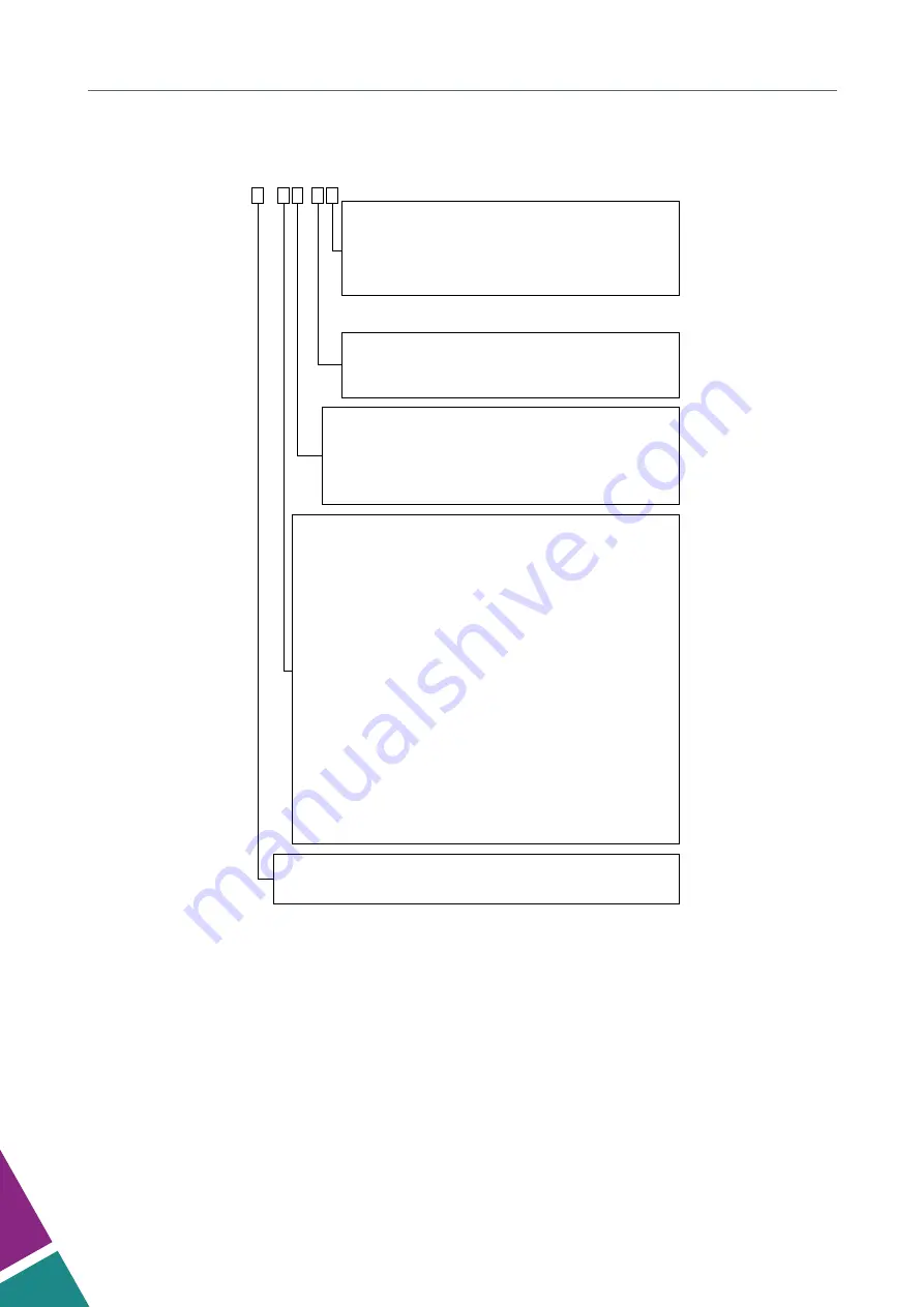
Product information Wireless data loggers
Data loggers in waterproof 120 x 80 mm housing for outdoor use
HD35ED W .
ANTENNA AND SOLAR RADIATIONS SHIELD:
Blank =
internal antenna (without shield and clamping) (*)
W =
fixed external antenna (without shield and clamping)
X =
fixed external a shield and clamping (**)
Y =
external antenna with 3 m cable (without shield and clamping)
Z =
external antenna with 3 m cable + shield and clamping (**).
RADIO FREQUENCY:
E
= 868 MHz radio frequency (Europe)
U
= 902-928 MHz radio frequency (U.S.A. and Canada)
J
= 915.9-929.7 MHz radio frequency (Japan)
PROBE TYPE:
H
= terminal header inputs for standard analog sensors
MB
= input for RS485 MODBUS-RTU sensors
TC
= probe with cable
TV
(or
TVI
) = fixed vertical probe without cable
TCV
= probe with cable + fixed vertical probe without cable
MEASURED QUANTITIES :
See table 6A for the combinations of quantities measured by the available data loggers. .
Other models
can be supplied upon request.
1
= humidity
4b
= atmospheric pressure (Barometer)
N
= temperature NTC10K sensor:
N/1
=1 channel,
N/2
=2 channels,
N/3
=3 channels
7P
= temperature Pt100/Pt1000 sensor:
7P/1
=1 channel,
7P/2
=2 channels,
7P/3
=3 channels
K
= temperature thermocouple sensor:
K/4
=4 channels
P
= rainfall quantity
R
= solar radiation (pyranometer)
S
= soil volumetric water content
L
= leaf wetness
V
= acceleration
B
= carbon dioxide (CO2) low range (5,000 ppm)
B2
= carbon dioxide (CO2) high range (10,000 ppm)
I
= illuminance low range (20,000 lux)
I2
= illuminance high range (200,000 lux)
F
= photons flow in the chlorofyll range (PAR)
WBGT
= WBGT index
Blank
= analog or RS485 MODBUS-RTU standard sensors
LCD:
Blank
= without LCD
L
= with custom LCD
(*) In HD35ED…J models, the antenna can be internal only in models measuring CO2 and/or illuminance.
(**) Option not available for models measuring CO2 and/or illuminance.
46


