background image

8

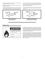
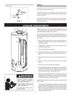
FIGURE 3.

A gas water heater cannot operate properly without the correct amount
of air for combustion.  Do not install in a confined area such as a closet,
unless you provide air as shown in the “Locating The New Water
Heater” section.  Never obstruct the flow of ventilation air.  If you have
any doubts or questions at all, call your gas supplier.  Failure to provide
the proper amount of combustion air can result in a fire or explosion
and cause death, serious bodily injury, or property damage.

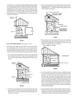
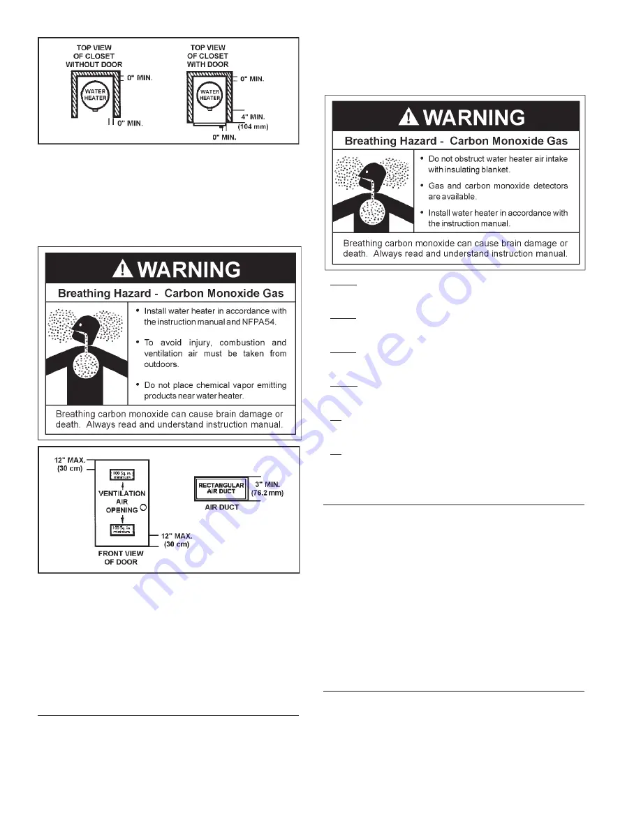
FIGURE 4.

If this water heater will be used in beauty shops, barber shops, cleaning
establishments, or self-service laundries with dry cleaning equipment,
it is imperative that the water heater or water heaters be installed so
that combustion and ventilation air be taken from outside these areas.

Propellants of aerosol sprays and volatile compounds, (cleaners,
chlorine based chemicals, refrigerants, etc.) in addition to being highly
flammable in many cases, will also change to corrosive hydrochloric
acid when exposed to the combustion products of the water heater.
The results can be hazardous, and also cause product failure.

INSULATION BLANKETS

Insulation blankets are available to the general public for external use
on gas water heaters but are not necessary with these products.  The
purpose of an insulation blanket is to reduce the standby heat loss
encountered with storage tank heaters.  Your water heater meets or
exceeds the National Appliance Energy Conversation Act standards
with respect to insulation and standby loss requirements, making an
insulation blanket unnecessary.

Should you choose to apply an insulation blanket to this heater, you
should follow these instructions (For identification of components
mentioned below, see Figure 1).  Failure to follow these instructions
can restrict the air flow required for proper combustion, potentially
resulting in fire, asphyxiation, serious personal injury or death.

• Do not apply insulation to the top of the water heater, as this will

interfere with safe operation of the draft hood.

• Do not cover the outer door, thermostat or temperature & pressure

relief valve.

• Do not allow insulation to come within 2" (50.8 mm) of the floor to

prevent blockage of combustion air flow to the burner.

• Do not cover the instruction manual.  Keep it on the side of the

water heater or nearby for future reference.

• Do obtain new warning and instruction labels from the manufacturer

for placement on the blanket directly over the existing labels.

• Do inspect the insulation blanket frequently to make certain it

does not sag, thereby obstructing combustion air flow.

COMBUSTION AIR AND VENTILATION FOR
APPLIANCES LOCATED IN UNCONFINED SPACES

UNCONFINED SPACE

 is space whose volume is not less than

50 cubic feet per 1,000 Btu per hour (4.8 cm per kW) of the aggregate
input rating of all appliances installed in that space.  Rooms
communicating directly with the space in which the appliances are
installed, through openings not furnished with doors, are considered a
part of the unconfined space.

In unconfined spaces in buildings, infiltration may be adequate to provide
air for combustion, ventilation and dilution of flue gases.  However, in
buildings of tight construction (for example, weather stripping, heavily
insulated, caulked, vapor barrier, etc.), additional air may need to be
provided using the methods described in “Combustion Air and Ventilation
for Appliances Located in Confined Spaces.”

COMBUSTION AIR AND VENTILATION FOR
APPLIANCES LOCATED IN CONFINED SPACES

CONFINED SPACE

 is a space whose volume is less than 50 cubic feet

per 1,000 Btu per hour (4.8 cm per kW)  of the aggregate input rating of
all appliances installed in that space.

A. ALL AIR FROM INSIDE BUILDINGS: 

(See Figure 4 and 5)

The confined space shall be provided with two permanent openings

communicating directly with an additional room(s) of sufficient volume
so that the combined volume of all spaces meets the criteria for an

Summary of Contents for RESIDENTIAL GAS WATER HEATERS

Page 1: ...RCHASED IFYOUAREUNSUCCESSFUL PLEASEWRITETOTHECOMPANYLISTEDONTHERATINGPLATEONTHEWATERHEATER RESIDENTIAL GAS WATER HEATERS For Your Safety ANODORANTISADDEDTOTHEGASUSED BYTHISWATERHEATER C3 Technology Ga...

Page 2: ...it relates to the installation of gas fired water heaters The qualified installer must also be familiar with the design features and use of flammable vapor ignition resistant water heaters and have a...

Page 3: ...3 GENERALSAFETY...

Page 4: ...t follow the safety rules the water heater will not operate properly It could cause DEATH SERIOUSBODILYINJURYAND ORPROPERTYDAMAGE This manual contains instructions for the installation operation and m...

Page 5: ...BY LOCAL CODES FIGURE1 J Drip Leg Sediment Trap K Inner Door L Outer door M Union N Inlet Water Shut off Valve O Cold Water Inlet P Inlet Dip Tube Q Temperature Pressure Relief Valve R Rating Plate S...

Page 6: ...thers These include the elderly children the infirm or physically mentally handicapped If anyone using hot water in your home fits into one of these groups or if there is a local code or state law req...

Page 7: ...alarm or turn off the incoming water to the water heater when leakage is detected Sensors mounted in the drain pan that turn off the water supply to the entire home when water is detected in the drain...

Page 8: ...sulting in fire asphyxiation serious personal injury or death Do not apply insulation to the top of the water heater as this will interfere with safe operation of the draft hood Do not cover the outer...

Page 9: ...uipment in the enclosure see Figure 7 3 When communicating with the outdoors through horizontal ducts each opening shall have a minimum free area of 1 square inch per 2 000 Btu per hour 11 cm2 kW of t...

Page 10: ...quires water for space heating at temperatures higher than required for domestic water purposes a tempering valve must be installed Please refer to Figure 2 for suggested piping arrangement Water supp...

Page 11: ...installed directly into the fitting of the water heater designed for the relief valve Position the valve downward and provide tubing so that any discharge will exit only within 6 inches 153 mm above...

Page 12: ...replacement heater installations where using pre existing venting venting must be inspected for obstructions and if deterioration is present venting must be replaced To insure proper venting of this g...

Page 13: ...ving all gas appliances is used also turn off the gas at each appliance Leave all gas appliances shut off until the water heater installation is complete A gas line of sufficient size must be run to t...

Page 14: ...valve of the water heater can be accomplished by either of the two methods shown in Figures 12 and 13 A sediment trap shall be installed as close to the inlet of the water heater as practical at the...

Page 15: ...urner It can be located by looking through the glass view port while pressing the piezo ignitor button several times Look for a spark at the pilot location see Figure D 9 Once the pilot has been found...

Page 16: ...tizing needs can scald and permanently injure you upon contact Some people are more likely to be permanently injured by hot water than others These include the elderly children the infirm or physicall...

Page 17: ...ner area during heating and cooling periods and should be considered normal See Condensation in this section OPERATIONAL CONDITIONS SMELLYWATER In each water heater there is installed at least one ano...

Page 18: ...eplaced At least once a year a visual inspection should be made of the main burner and pilot burner see Figure 16 PERIODIC MAINTENANCE You should check for sooting Soot is not normal and will impair p...

Page 19: ...o completely reset and continues to release water immediately close the cold water inlet to the water heater follow the draining instructions and replace the temperature pressure relief valve with a n...

Page 20: ...and drip onto the burner or run on the floor This is common at the time of start up after installation and when incoming water is cold I Water in the water heater bottom or on the floor may be from c...

Page 21: ...optional 26 Instruction Manual 27A Nipple with Heat Trap 27B Secondary Anode with Heat Trap Not Shown Now that you have purchased this water heater should a need ever exist for repair parts or service...

Page 22: ...functions Thermocouple TCO malfunction Replace pilot assembly High ambient room temperature Contact a service agency to determine cause BURNER WILL NOT Dirty or clogged air intake screen Clean and rei...

Page 23: ...23 NOTES...

Page 24: ...24...

Reviews: