Blow Applicator with Swing Cylinder
cab - Produkttechnik GmbH & Co KG
17
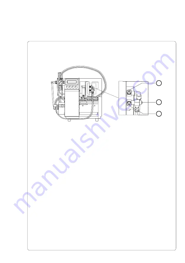
Throttle Valves at the Cylinder
1
2
3
Fig. 5.2b Throttle Valves at the Cylinder
The setting of the cylinder can be regulated via two throttle valves (
1,
3
). Those valves regulate the speed with which the compressed air
escapes the two air containers.
The valves are adjustable by turning the throttle screws. Turning
clockwise will close the valves.
A wider opening of the bottom valve (
3
) speeds up the pad moving
from the starting position to the labelling position, a wider opening of
the top valve (
1
) accelerates the return movement.
A third throttle valve (
2
) limits the speed of the compressed air
streaming into the bottom air container. By switching the machine on
this valve damps the first movement of the pad into the starting
position. At this time the top air container is empty, therefore, the
setting of the top throttle valve (
1
) is ineffective to damp this move-
ment.


