34
34
10
Spare Parts
10.1
Retainer Assembly
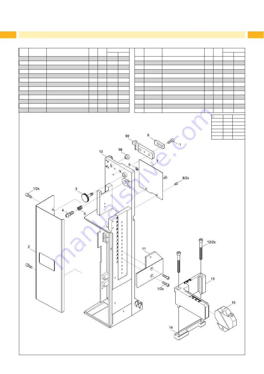
Fig. 35
Retainer assembly - spare parts
No
Part No.
Description
PU
Note
Serial No.
from
to
1
5902489.001 Screw DIN7984-M4x8
10
2.1 5964129.001 Cover
1
L
2.2 5964260.001 Cover
1
R
3
5964367.001 Knurled Screw
1
4
5964104.001 Set Screw
1
5
5904544.001 Spring
10
6
5964090.001 Bar
1
7.1 5964429.001 Plate
1
L
7.2 5964438.001 Plate
1
R
8
5902021.001 Screw DIN7991-M3x6
10
9
5903525.001 E-Ring DIN6799-4
10
10.1 5964036.001 Base Plate
1
L
10.2 5964185.001 Mounting Plate
1
R
No
Part No.
Description
PU
Note
Serial No.
from
to
11.1 5964318.001
Adapter Profile
1
A
/
B
11.2 5970013.001
Adapter Profile
1
L
/C
11.3 5970014.001
Adapter Profile
1
R
/
C
12
5902167.001 Screw DIN912 M5x50
10
13.1 5964312.001 Crossbeam
1
L
/
D
13.2 5964331.001 Crossbeam
1
R
/
D
13.3 5964332.001 Crossbeam
1
L
/
E
13.4 5964333.001 Crossbeam
1
R
/
E
14.1 5964310.001 Clamping Element
1
L
14.2 5964328.001 Clamping Element
1
R
15
5964062.001 Binder
1
98
5966530.001 Eccentric
1
99
5966529.001 Hinges
1
Notes
L
L
R
R
A
200H
B
300H
C
400H
D
4114
E
4116
Summary of Contents for 4114 Series
Page 1: ...Made in Germany 4114 4116 Stroke Applicator Service Manual ...
Page 40: ...40 40 11 Drawings 11 2 Pneumatic Drawing Type 4114 Fig 41 Pneumatic drawing type 4114 ...
Page 41: ...41 11 Drawings 11 3 Pneumatic Drawing Type 4116 Fig 42 Pneumatic drawing type 4116 ...
Page 42: ...42 42 11 Drawings 11 4 Label Position Type 4114L 4116L Fig 43 Label position 4414L 4116L ...
Page 43: ...43 11 Drawings 11 5 Label Position Type 4114R 4116R Fig 44 Label position 4114R 4116R ...


