16
16
6.2
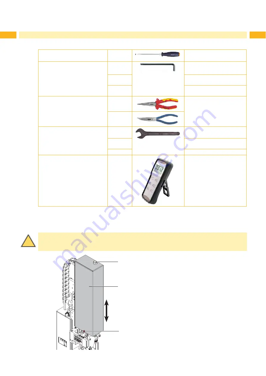
Tools
Screwdriver with parallel blade
2.5
To adjust the throttle valves and
product sensor
Hexagon key L-wrench
0.8
To adjust the sensors
(in contents of delivery)
2.5
For matched norm parts
(in contents of delivery)
4
Pad adjustments
Changing pad
Flat-round nose
straight
To mount/dismount tubes
angled
Open spanner
SW 8
To change the throttle valves
SW 13
Setting the spring power on the
adapter bolt
SW20
Changing the cylinder
Manometer
± 7 bar
Air pressure control
Table 3
Tools
6.3
Mounting and Dismounting the Cover
To initiate the applicator or for adjustments it is necessary to dismount the cover (2).
After these works are finished remount the cover.
!
Warning!
Do not operate the applicator without cover (2).
Only dismount the cover when servicing the applicator.
2
3
1
Dismount
1. Loosen screw (3).
2. Lift off cover (2).
Mount
3. Move the cover (2) over the cylinder assembly.
4. Put in the cylinder (1) through the hole in the cover
(2).
5. Tighten screw (3) to fasten the cover (2).
Fig. 8
Cover
Summary of Contents for 4114 Series
Page 1: ...Made in Germany 4114 4116 Stroke Applicator Service Manual ...
Page 40: ...40 40 11 Drawings 11 2 Pneumatic Drawing Type 4114 Fig 41 Pneumatic drawing type 4114 ...
Page 41: ...41 11 Drawings 11 3 Pneumatic Drawing Type 4116 Fig 42 Pneumatic drawing type 4116 ...
Page 42: ...42 42 11 Drawings 11 4 Label Position Type 4114L 4116L Fig 43 Label position 4414L 4116L ...
Page 43: ...43 11 Drawings 11 5 Label Position Type 4114R 4116R Fig 44 Label position 4114R 4116R ...


