31
6.12
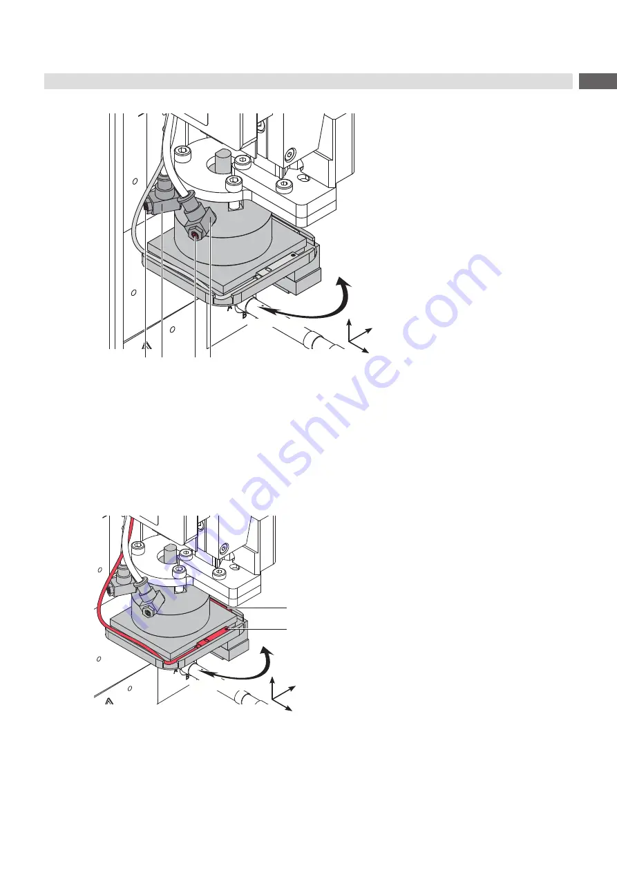
Lift Speed of Cylinder R
2
3
1
4
swing in
swing out
Fig. 35
One-way flow control valve of cylinder R
Adjust speed as necessary.
To increase the outward movement speed of cylinder R in the direction of the labeling position turn the screw (1)
of valve (2) counterclockwise.
To increase the inward movement speed of cylinder R in the direction of the labeling position turn screw (3) of
valve (4) counterclockwise.
6.13
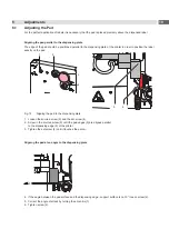
Sensors on Cylinder R
2
1
swing in
swing out
The sensors of cylinder R show the position of the cylinder in
the state of label take-up and labeling position.
•
Place the sensor start position (1) so that it is triggered
if the cylinder is completely swiveled in and releases as
soon as the cylinder moves from the start position.
•
Place the sensor end position (2) so that it is triggered if
the cylinder is completely swiveled out and releases as
soon as the cylinder leaves the end position.
Fig. 36
Sensors on cylinder R
y
x
z
y
x
z
Summary of Contents for 4214 Series
Page 1: ...Service Manual 4214 MADE IN GERMANY Stroke Turn Applicator...
Page 39: ...39 9 Drawings 9 2 Pneumatic Drawing Type 4214 Fig 43 Pneumatics type 4214...
Page 40: ...40 40 9 Drawings 9 3 Labeling Position Type 4214 L Fig 44 Labeling position 4214L...
Page 41: ...41 9 Drawings 9 4 Label Position Type 4214 R Fig 45 Labeling position 4214R...


