background image

12

13

Adjustments

Note!

The alignment of the applicator to the printer is fixed according to factory standards and should not be 

altered to ensure a safe label application. Only the angle to the printer may be changed. 

4.1 

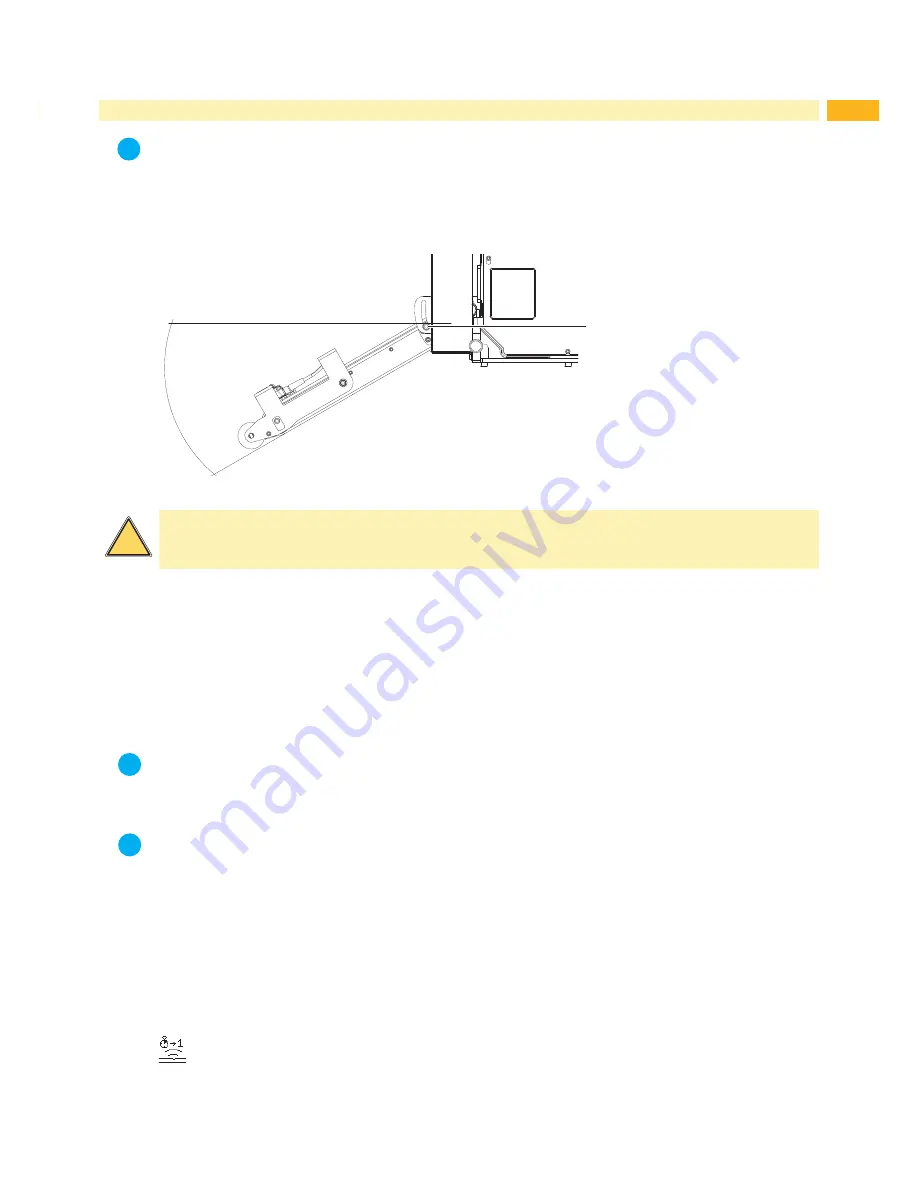
Setting the Angle to the Printer

1

max 30°

Fig.9     

Setting the angle to the printer

Warning!

Take care when loosening screw (1). The device drops due to its own weight.


Loosen screws (1) to adjust the angle and thus the depth of the applicator to the printer.


Set the angle or depth of the product and tighten the screws (1). 

 4.2 Adjust the Setup of the Printer

4.2 

Adjusting the Setup of the Printer

The configuration parameters of the applicator can be found in the menu 

Setup > Machine param. 

Speed

Note! 
The speed of the belt and the label transportation will set by the parameter 

Support del. OFF

.  

The value is displayed in ms and not in real value used mm/s.

Note! 
It's necessary to set exact the values in the table.  
Deviations will result in automatic defaulting back to the standard value of 100.

Parameter to set the speed of the belts. 

Four steps are available.


100 ms :       100   mm/s speed of the transportation belt


150 ms :       150   mm/s speed of the transportation belt


220 ms :       220   mm/s speed of the transportation belt


300 ms :       300   mm/s speed of the transportation belt


500 ms :       500   mm/s speed of the transportation belt


> Support del. OFF

i

i

i

!

Summary of Contents for 5314

Page 1: ...MF Made in Germany Operator s Manual 5314 5316 Vacuum Belt Applicator...

Page 2: ...ck www cab de for the latest update Terms and conditions Deliveries and performances are effected under the General conditions of sale of cab Operator s Manual for the following products Germany cab P...

Page 3: ...1 Standard Operation 9 3 2 Cleaning 9 3 3 Mounting 10 3 4 Power Supply of the Devices 11 3 5 Start Signal via External Sensor 11 3 6 Mounting dismounting the Applicator 12 4 Adjustments 13 4 1 Settin...

Page 4: ...nd the recognized safety rules However danger to life and limb of the user or third parties and or damage to the device and other tangible assets can arise during use The device may only be used for i...

Page 5: ...nel or service technicians Unauthorized interference with electronic modules or their software can cause malfunctions Other unauthorized work on or modifications to the device can also endanger operat...

Page 6: ...ng on the surface on the surface Label width mm 20 114 46 174 Label height mm 60 356 60 356 Product during labeling in motion Labeling on the product from top from below from the side Product distance...

Page 7: ...tor for a start sensor 3 Power cable Voltage to the printer 4 SUB D 15 Interface to the printer 5 Power module 6 Pressure roller 7 Sensor 8 Fans 9 Screws to adjust the angle of the applicator 10 Contr...

Page 8: ...able clip self adhesive 4x 3 Screws to mount on the printer 4 Documentation 2 5 i Note Please keep the original packaging in case the applicator must be returned Attention The device and printing mate...

Page 9: ...print job has been interrupted with the cancel key Synchronizing is not necessary when the print head was not lifted between print jobs This also applies if the printer was powered down between print...

Page 10: ...its side or back to gain access to the bottom of it 4 Put the hole of mounting plate 9 over the pin 3 5 Connect SUB D 9 male connector 8 to the female connector 6 of the printer 6 Swing the applicator...

Page 11: ...ly the printer and not the applicator is switched on the error message Air pressure ins will appear 5 For better cable guidance and organization use the four self adhesive cable clips 5 within the sco...

Page 12: ...n caused by the weight of the applicator 1 To dismount the applicator 5 for cleaning or loading material pull both locking pins 3 outward from the control unit 2 Raise the applicator 5 with pulled out...

Page 13: ...inter 4 2 Adjusting the Setup of the Printer The configuration parameters of the applicator can be found in the menu Setup Machine param Speed Note The speed of the belt and the label transportation w...

Page 14: ...be ajusted via the parameter Support del ON 4 3 Signals The signal DREE will start the print the label and move it to the reflex sensor before the pinch roller The signal START will feed the label pa...

Page 15: ...tion infront of the princh roller before the START signal was received Upper position The label has not arrived at the sensor area 5 sec after printing or it wasn t detected Air pressure ins Applicato...

Page 16: ...y EN ISO 12100 2010 EN ISO 13849 1 2015 EN 60950 1 2006 A11 2009 A12 2011 A1 2010 A2 2013 Other Relevant Directives Directive 2014 30 EU relating to electromagnetic compatibility Directive 2011 65 EU...

Page 17: ...by us being made to any device as designated below this statement shall thereby be made invalid Device Vacuum Belt Applicator Type 5314 5316 Applied EU Regulations Applied Standards Directive 2014 30...

Reviews: