42
A 3
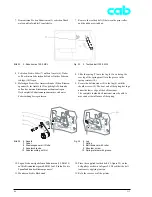
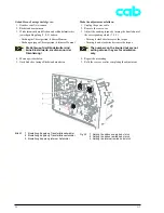
Neue Leiterplatte CPU einbauen:
1. Untere Steckverbinder (3 bis 6) in die Leiterplatte CPU
einstecken.
2. Leiterplatte nach oben schwenken und mit 4 Schrauben
festschrauben.
3. Seitliche Steckverbinder (7 bis 11) einstecken.
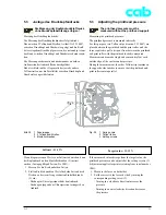
4. Etikettenlichtschranke nach Abschnitt 2.4.2 abgleichen.
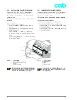
5. Transferfolienlichtschranke nach Abschnitt 2.4.3
abgleichen.
6. Wurde der NVRAM gesichert: NVRAM nach Ab-
schnitt 2.4.5 einlesen und ggf. Konfigurations-
einstellungen vornehmen.
7. Montieren Sie die Rückwand.
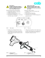
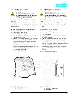
Bild 28
3 Etikettenlichtschranke
4 Kleinspannungseingang vom Netzteil
5 Druckkopf-Leistungsanschluss
6 Druckkopf-Logikanschluss
7 Motor
8 Kopfverriegelung
9 USB-Peripherie
10 USB-Peripherie
11 Bedienfeld
Fig. 28
3 Label edge sensor
4 Low-voltage input from power pack
5 Printhead power connector
6 Printhead logic connector
7 Motor
8 Head lock
9 USB peripherals
10 USB peripherals
11 Control panel
Fitting a new CPU PCB:
1. Insert the plugs (3 to 6) into the underside of the CPU
PCB.
2. Swivel the PCB upwards and secure with four screws.
3. Insert the plugs (7 to 11) into the sides of the PCB.
4. Adjust the label edge sensor as described in
section 2.4.2.
5. Adjust the transfer ribbon sensor as described in
section 2.4.3.
6. If the NVRAM has been saved, read in the NVRAM as
described in section 2.4.5, make configuration settings
if necessary.
7. Refit the rear cover of the printer.


