background image

8

A8

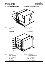
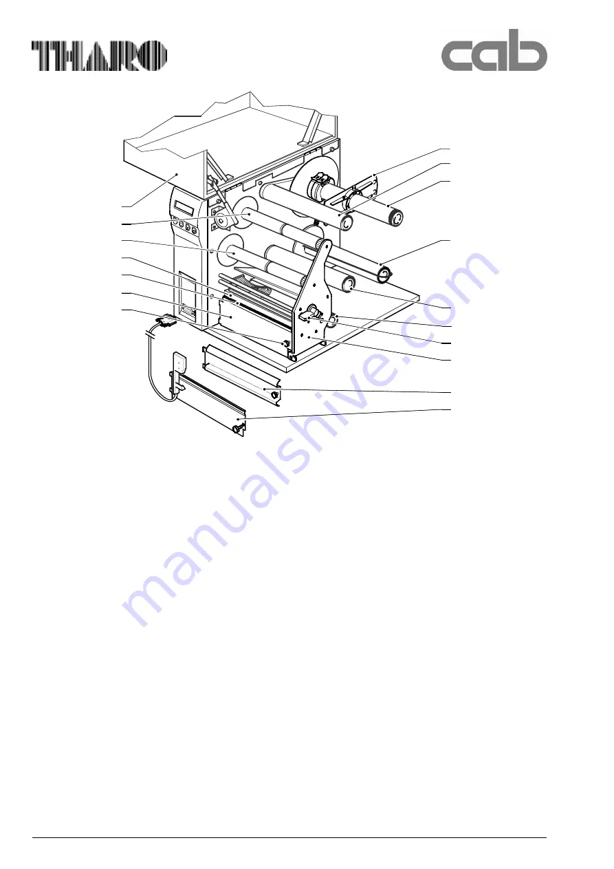
Bild 3

1 Deckel
2 Abwickler Transfer
3 Aufwickler Transfer
4 Druckkopf
5 Druckwalze
6 Abreißkante
7 Rändelschraube
8 Flansch
9 Schwenkhebel

10 Etikettenabwickler
11 Interner Aufwickler mit Klemmbügel
12 Umlenkrolle
13 Umlenkachse
14 Hebel zur Druckkopfverriegelung
15 Versteifung
16 Umlenkblech
17 Spendesensor, Option

Figure 3

1 Cover
2 Ribbon supply hub
3 Ribbon take up hub
4 Printhead
5 Print roller
6 Tear-off plate
7 Knurled screw
8 Flange
9 Swing arm

10 Media hub
11 Internal rewinder
12 Media assist bar
13 Rewind guide axle
14 Printhead lever
15 Plate
16 Rewind guide plate
17 Present sensor, (Option)

1

2

3

4

5

6

7

8

9

10

11

12

13

14

15

16

17

Summary of Contents for A8

Page 1: ...Ausgabe Edition 2 00 Transferdrucker Transfer Printer A 8 A 8 A 8 A 8 A 8 Serviceanleitung Service Manual ...

Page 2: ...ais Gesellschaft für Tharo Systems Inc Computer und Automations 2866 Nationwide Parkway Bausteine mbH Co KG P O Box 798 cab Produkttechnik GmbH Co KG Brunswick OH 44212 0798 Postfach 1904 D 76007 Karlsruhe Web http www tharo com Wilhelm Schickard Str 14 D 76131 Karlsruhe E mail tharo tharo com Telefon 49 0 721 66 26 00 Tel 1 330 273 4408 Telefax 49 0 721 66 26 249 Fax 1 330 225 0099 Web http www c...

Page 3: ...the label edge sensor 45 6 8 Adjusting the present sensor accessory 45 Inhaltsverzeichnis 1 Einführung 1 1 Hinweise für den Benutzer 3 1 2 Wichtige Informationen 3 1 3 Allgemeine Sicherheitshinweise 4 1 4 Sicherheit beim Umgang mit Elektrizität 5 1 5 Leistungsmerkmale 6 1 6 Lieferumfang 6 1 7 Teile des Etikettendruckers 7 1 8 Optionen 9 1 9 Technische Daten 10 2 Selbsttest 2 1 Überprüfung der Ansc...

Page 4: ...Blockschaltbild B Stromlaufpläne C1 C9 Belegungspläne D1 D2 Steckerplan E Steckerbelegung F1 F4 Stichwortverzeichnis 7 Trouble diagnosis and correction 7 1 Errors during printing 46 7 2 Failure of device functions 48 7 3 Permanently displayed hardware errors 50 8 Functional description 8 1 PCB A8 kpl Art Nr 553 9294 51 8 2 Control panel 51 8 3 Sensors 51 8 3 1 Label edge sensor 51 8 3 2 Ribbon sen...

Page 5: ...used to characterize the kind of danger See a sample for the risk of electric shock WARNING Mortal danger by electric shock Unplug power cord before opening the cover 1 Einführung 1 1 Hinweise für den Benutzer Dieses Handbuch ist für das qualifizierte Service und Wartungspersonal vorgesehen Es beinhaltet technische Informationen die sich auf die Hardware und den mechanischen Teil des Etikettendruc...

Page 6: ...derVerwendungvonLösungsmitteln Reinigern odersonstigenChemikalien generellbeieinermöglichenGefährdungderAugen aufgrundderArbeitsbedingungen BringenSienachAusführungderWartungsarbeiten sämtlicheSchutzvorrichtungenwieAbdeckungen SicherheitshinweiseundErdungskabelwiederan TauschenSiefehlerhafteoderunbrauchbargewordene Teileaus 1 3 General safety instructions Follow the general safety rules below Keep...

Page 7: ...e Gefahrenquellen wiez B feuchteFußböden defekte Verlängerungskabel fehlerhafteSchutzleiterverbin dungenusw BeiUnfällenmitElektrizität GehenSievorsichtigvorundvermeidenSiedie GefährdungdereigenenPerson SchaltenSiedenStromab FordernSieärztlicheHilfe Notarzt an LeistenSiegegebenenfallsErsteHilfe 1 4 Safe handling of electricity Follow the additional instructions below when handling electricity Findo...

Page 8: ...Seite durch mindestens 5 cm Dämmmaterial gegen Stoß geschützt werden ACHTUNG Sachschäden am Drucker bei nicht zweckent sprechender Verpackung 1 5 Features The A8 Label Printer is a direct thermal and thermal transfer printer offering the following features longlifetime intendedforpermanentindustrialuse longwearingbearingsandconveyorrollersformaximum printqualityandalonglifetime easyandcomfortableo...

Page 9: ...cherkarte 2 Parallele Schnittstelle Centronics 3 Serielle Schnittstelle 4 Anschluss externe Tastatur 5 Spannungswähler 6 Netzschalter 7 Netzbuchse 8 Netzeingangsmodul Figure 2 Backside view A8 1 PCMCIA memory module slot 2 Parallel port Centronics 3 Serial port 4 External keyboard port 5 Input voltage selector 6 Power switch 7 Power supply 8 Fused Main Connector 1 7 Teile des Etikettendruckers 1 7...

Page 10: ...enkachse 14 Hebel zur Druckkopfverriegelung 15 Versteifung 16 Umlenkblech 17 Spendesensor Option Figure 3 1 Cover 2 Ribbon supply hub 3 Ribbon take up hub 4 Printhead 5 Print roller 6 Tear off plate 7 Knurled screw 8 Flange 9 Swing arm 10 Media hub 11 Internal rewinder 12 Media assist bar 13 Rewind guide axle 14 Printhead lever 15 Plate 16 Rewind guide plate 17 Present sensor Option 1 2 3 4 5 6 7 ...

Page 11: ...er Schneidmesser Spendesensor Schneid Spendeadapter Speicherkarten ExterneTastatur EtikettiersoftwareEASYLABELforWindows 1 8 Optional features The optional features below are available for the A8 Label Printer ExternalRewinder CutterAssembly PresentSensor Cut Peel offAdapter PCMemory Cards ExternalKeyboard LabelDesignSoftwareEASYLABELforWindows ...

Page 12: ... 39 Code 93 Code 128 A B C Codabar FIM HIBC Interleaved2 5 Ident LeitcodederdeutschenPostAG MSI PlesseyPostnet 1 9 Technical Specifications Type Thermal Thermaltransferprinter Printhead Thinfilmtransferhead Printhead Resolution 203dpi 8dots mm Dots Line 1728 Printingwidth 8 5 in 216mm Printingspeed 50 75 100 125 mm s CharacterSets 5bitmapfontsincl OCR AandOCR B 3scaleablefonts SpeedoTM internal Sp...

Page 13: ...32 8 bit 1 200 115 200 Baud RS 422 8 bit 1 200 230 400 Baud RS 485 8 bit 1 200 230 400 Baud RS 232 485 Host 8 bit 1 200 115 200 Baud Parallel Centronics KeyboardinterfacePS 2 Peripherialinterface forlabelcutterorpresentsensor Testfeatures Systemtestwhenswitchingon Selftestwithprintoutoffirmwaredata andsystemparameters Labelsand directthermalpaper continuouspaper standardpaperlabels synthetics PE P...

Page 14: ...htigkeit Transport 25 Cbis 70 C beimax 95 Luftfeuchtigkeit Lagerung 5 Cbis40 C bei5 85 Luftfeuchtigkeit Material Gapsensor see through Bottom recognition reflectivesensor Distancetopaper edge 12to2in 3bis52mm Transferribbon Length max 17 7in 450m Outsidediameter max 3in 80 mm Corediameter 1in 25mm Inksideinorinksideout Backfeed Inordertoalwaysstartprintjobfromthe frontedgeofthefirstlabelthestripma...

Page 15: ...inschalten des Druckers die Taste ONL gedrückt halten bis der System test abgeschlossen ist Im Display erscheint die Anzeige Testausdruck Ein Abbruch des Testausdrucks ist durch Drücken der Taste CAN möglich 2 Self test The A 8 Label Printer has a built in self test which makes troubleshooting easier and gives information about the default configuration of the device 2 1 Checking the connecting vo...

Page 16: ...atus information 2 Availiable character sets 3 Test pattern 4 Firmware version 5 Bar code with test information Bild 4 Selbsttestausdruck 1 Setup Statusinformationen 2 Schriftarten 3 Testmuster 4 Firmware Version 5 Barcode mit Testinformationen 2 3 Self test explanation 5 4 1 2 3 ...

Page 17: ...alprogramm zeigt folgendes Menü auf dem Bildschirm 3 Internal Setup Apart from the setup facilities that can be accessed by the user see manual the printer has an internal setup which is to be used by service personnel only In order to use the internal setup you need a terminal application Therefore you can use 121 or TELIX on a DOS PC Windows Terminal on a Windows PC ZTERM on a Macintosh Connect ...

Page 18: ... Setup supports the printhead alignment There will be a grid test pattern printed every 5 seconds After keying a 2 in Terminal to select this option the following message will appear 3 3 3 Zähler zurücksetzen Der Zählersatz beinhaltet Betriebsdauer Transferdruckleistung und Thermodruckleistung Die angezeigte Wertezeile enthält die Daten die für den Gesamtzeitraum seit der Inbetriebnahme des Geräts...

Page 19: ... rotate the ribbon unwinder press any key if values don t change any more 7 136 Using 39 104 Please remove label stock any key Als erstes findet der Abgleich der Transferbandlicht schranke statt Nach Drücken der Taste Y erscheinen im Terminalprogramm zwei Zahlenwerte z B 98 99 Durch Drehen des Transferbandabwicklers ändern sich diese Werte und erreichen nach kurzer Zeit ein Endniveau z B 7 136 Drü...

Page 20: ...56 61 Using 40 256 55 Finished adjustement Values 11 40 any key Der Strom der Sensordiode wird weiter erhöht bis die Messwerte am Empfänger unter den geänderten optischen Bedingungen den vorgebenen Grenzwert erneut erreichen Die beiden Grenzwerte des Diodenstroms 11 40 finden sich ebenfalls im Parameter Helligkeiten im Selbsttestaus druck wieder During the sensor adjustment the current of the diod...

Page 21: ...ern In einem solchen Fall ist es möglich die Protokollfehleranzeige auszuschalten ACHTUNG Protokollfehler die auf fehlhafte Pro grammierung zurückzuführen sind werden ebenfalls ignoriert Es besteht die Gefahr von Datenverlust Durch Betätigen der Taste 8 kann umgeschaltet werden zwischen den Anzeigen und 3 7 8 Ignore protocol errors In case of using older computer operating systems it is possible t...

Page 22: ...hädigt wird Diese Verzögerungszeit kann abgeschaltet werden um z B bei maschineller Entnahme den Durchsatz zu erhöhen Durch Betätigen der Taste A kann umgeschaltet werden zwischen den Anzeigen und Als Standard ist die Einstellung On zu wählen A Delay for peel off On A Delay for peel off Off and The On setting should be selected as standard 3 9 C 24 V on Normally the heat voltage is switched on dur...

Page 23: ...ws Having completed the internal setup the printer will now perform a reset and will be placed in the ONLINE mode You can now exit the Windows Terminal program if desired Nach Drücken von Taste P erscheint im Display die Ausschrift Please enter new PIN 0000 disables setup protection Geben Sie eine vierstellige Zahl z B 1111 ein Die Eingabe ist am Display nicht sichtbar Drücken Sie die ENTER Taste ...

Page 24: ...s Druckkopfes 4 Mit einem Reinigungsstift Schmutz und anhaftende Teilchen von der Druckoberfläche des Druckkopfes entfer nen 5 Druckkopf 2 bis 3 Minuten trocknen lassen 4 Maintenance 4 1 General cleaning Interior Duringnormaloperation mediadebrismay accumulatearoundtheprintermechanism Cleanawaythisdebrisregularlyusingasoft bristlebrushand orvacuumcleaner Exterior Theexteriorsurfacesmaybecleanedwit...

Page 25: ... Transferband aus dem Drucker entfernen 4 Mit einem sauberen Tuch und Alkohol alle Ablagerungen entfernen 4 3 Cleaning the print and guide rollers If the print and guide rollers become contaminated with dirt label adhesive or ink print quality may also be adversely affected To clean the rollers proceed as follows 1 Switch off printer open cover 2 Lift printhead to the upper position 3 Remove label...

Page 26: ...el 10x13 Uhrmacher Schraubendreher Set 6tlg Schlitz 1 4 1 8 2 3 3 3 Kreuzschlitz Gr 0 Gr 1 Hammer 100 g Hammer Kunststoff 22 g Flachzange 180 mm 5 Replacing Assembly Units 5 1 List of Recommended Tools For servicing the A 8 printer the following set of tools is recommended 1 cab special tools Test collar Art No 553 4199 Test collar Art No 553 9223 Teflon strip Art No 553 0687 2 Standard tools Stan...

Page 27: ...teigend 0 05 0 25 Fühllehre 13tlg 0 1 steigend 0 3 1 0 Federwaage 5 N Federwaage 25 N Snap ring pliers ZGG 0 Snap ring pliers ZGG 1 Diagonal cutters 5 12 in 130 mm Scissors Tweezers Feeler gauge 13 pcs increasing by steps of 05 05 25 Feeler gauge 13 pcs increasing by steps of 1 3 1 0 Spring scale 5 N Spring scale 25 N ...

Page 28: ...opfbaugruppe 2 Feststellschraube für Druckkopf 3 Hebel zur Druckkopfverriegelung 4 Versteifung 5 Kopfplatte 6 Stecker für Signal 7 Stecker Leistung Heizung 8 Druckkopf 9 Schrauben 5 2 Replacing the printhead and the printhead cable CAUTION Ground yourself to the chassis before you remove or install the printhead This will prevent a static discharge from your body through the printhead to ground Re...

Page 29: ...nged in the same manner after replacing the printhead 4 Pull both cables out of the clamp 1 5 Move the printhead slightly to the front until the plug connectors 6 7 are accessible ACHTUNG Oberfläche des Druckkopfes nicht zerkratzen Positionierungsstifte müssen bei Montage beidseitig einrasten 8 Kopfplatte mit Druckkopf in die Positionierstifte einsetzen Sicherstellen dass der Druckkopf richtig in ...

Page 30: ...g einrasten 11 Kopfplatte mit Druckkopf in die Positionierstifte einsetzen Sicherstellen dass der Druckkopf richtig in den Stiften geführt ist dann Feststellschraube 2 Bild 5 mit Hand leicht anziehen Dabei auf eine gute Anlage des Druckkopfes an die Halterung über die gesamte Fläche achten 12 Druckkopf mit Hebel 3 Bild 5 verriegeln und Feststellschraube 2 Bild 5 festschrauben 13 Beide Druckkopfkab...

Page 31: ...nrad groß 5 Riemenrad klein 6 Sicherungsring und Scheibe 7 Zahnriemen 8 Sicherungsring 9 Riemenrad groß Figure 7 1 Belt tensioner 2 Toothed belt 3 Belt tensioner 4 Pulley big 5 Pulley small 6 Snap ring and washer 7 Toothed belt 8 Snap ring 9 Pulley big 5 3 Replacing the print roller and rewind assist roller WARNING Mortal danger by electric shock Unplug power cord Replacing print roller 1 Open cov...

Page 32: ...ure 8 10 Tear plate 11 Thumbscrew 12 Printhead locking lever 13 Plate 14 Axle 15 E ring 11 Schrauben 20 aus dem Lagerblech 19 herausschrauben 12 Lagerblech 19 vorsichtig abziehen 13 Jeweilige Walze erneuern und in umgekehrter Reihenfolge montieren ACHTUNG Bund am kleinen Riemenrad 5 Bild 7 muss bei Montage zur Montagewand zeigen Lager 18 der Druckwalze 16 auf die neue Druckwalze aufschieben Bild 9...

Page 33: ... 5 4 Replacing the label edge sensor WARNING Mortal danger by electric shock Unplug power cord Replacing label edge sensor 1 Open cover open printhead swing the plate 13 downwards Remove label stock and transfer ribbon from the printer 2 Remove housing 3 Remove the plug 1 of the label sensor cable from the PCB A8 4 Open the cable clamps 2 and 3 and pull the label sensor cable out of the clamps 5 L...

Page 34: ... Abgleich Etikettenlichtschranke Internes Setup Abgleich Transferbandlichtschranke Internes Setup 12 Gehäuse montieren HINWEIS Bei Bedarf ein Firmware Update durch führen 5 5 Replacing the PCB A8 WARNING Mortal danger by electric shock Unplug power cord Replacing the A8 PCB NOTICE Before replacing the PCB A8 create a self test printout or note the setup parameters for further reference 1 Remove al...

Page 35: ...r im Abschnitt Wechsel der Rutschkupplungen 5 6 Replacing the slipping clutches WARNING Mortal danger by electric shock Unplug power cord The take up hubs for labels and transfer ribbon are coupled to the main drive by slipping clutches At the supply hubs for labels and transfer ribbon slipping clutches are used for a defined braking of the material unwind too A replacement of a clutch is necessar...

Page 36: ...n 6 Weiter im Abschnitt Wechsel der Rutschkupplungen Vorarbeiten für den Wechsel der Kupplung des Trans ferbandabwicklers 1 Deckel öffnen Druckkopf hochklappen Etiketten und Transferband aus dem Drucker entfernen 2 Gehäuse abschrauben 3 Weiter im Abschnitt Wechsel der Rutschkupplungen Preparation for the replacement of the slipping clutches at the label take up hub and the ribbon take up hub The p...

Page 37: ...rigieren 6 Die in der Vorbereitung des Kupplungswechsels gelösten Teile montieren 7 Wickelmoment der gewechselten Kupplung nach Abschnitt 6 5 justieren Bild 14 2 2 Gewindestifte 5 Nase 6 Anschließendes Teil A Nuttiefe Figure 14 2 2 Bolts 5 Lug 6 Adjoining part A Slot depth 1 2 3 4 1 3A A 2 5 6 Clutch replacement 1 Unscrew the knurled nut 1 Make sure that the springs 3 do not get lost 2 Loosen the ...

Page 38: ...ite 6 Arbeitschritte zur Optimierung des Druckbildes wiederholen bis das Druckbild in Ordnung ist 6 Alignings and Adjustings 6 1 Aligning the printhead For optimum print quality the line of heating elements on the printhead must be parallel and aligned correctly to the print roller This alignment has already been performed in the factory Nevertheless it may become necessary to adjust it A misalign...

Page 39: ...37 A 8 Bild 15 1 Justageschrauben 2 Feststellschraube für Druckkopf 3 Versteifung Figure 15 1 Aligning screws 2 Locking screw 3 Plate 3 2 1 1 ...

Page 40: ...etten drehen Sie den Exzenter 1 in Richtung8derSkala 6 DadurchwirdderDruckkopf 3 stetig angehoben Überprüfen Sie zur Optimierung die GleichmäßigkeitdesDruckbildes HINWEIS Eine Fehljustage der Druckkopfab stützung kann auch zur Faltenbildung im Transferbandlauf führen 6 2 Adjusting the printhead support CAUTION Wear of the printhead Danger of early wear of the printhead if there is a continuous con...

Page 41: ...imUhrzeigersinnwird die Kraft erhöht 6 3 Adjusting the printhead pressure NOTICE Perform the measuring of the printhead pressure when the printhead support is deactivated The printhead pressure is measured indirectly at both ends of the printhead A Teflon ribbon 2 item ID 553 0687 must be positioned between the printhead and the print roller Measure the strength which is necessary to pull the ribb...

Page 42: ...etten sind mit Rutschkupplungen in den Hauptantrieb eingekoppelt An den Abwicklern für Transferband und Etiketten werden als Bremsen ebenfalls Rutschkupplungen eingesetzt Die korrekte Einstellung der Momente dieser Kupplungen ist notwendig für a die Vermeidung von Falten im Transferbandlauf Justage des Moments am Transferbandabwickler b eine exakte Mitnahme des Transferbandes beim Etikettentranspo...

Page 43: ...ontieren Measuring the torque at the ribbon supply hub The torque is measured by determining the traction using a test collar Part No 553 4199 at the supply hub The physical relation between torque and traction is as follows M F x r M torque F traction r radius of test collar 1 2 in 30 mm Set values Msupply 5 4 5 7 Ncm Fsupply 1 8 1 9 N Measure adjust as follows 1 Remove the transfer ribbon from t...

Page 44: ...ontieren 6 5 7 N 1 5 6 7 Bild 20 1 Federwaage 5 Prüfkörper 553 4199 6 Transferbandaufwickler 7 Rändelmutter an Kupplung Figure 20 1 Spring scale 5 Test collar 553 4199 6 Ribbon take up hub 7 Knurled nut at the clutch Measuring the torque at the ribbon take up hub The torque is measured by determining the traction using a test collar Part No 553 4199 at the supply hub The physical relation between ...

Page 45: ...tage Kappe montieren Bild 21 1 Federwaage 8 Etikettenabwickler 9 Prüfkörper 553 9223 10 Kappe 11 Rändelmutter Figure 21 1 Spring scale 8 Media supply hub 9 Test collar 553 9223 10 End cap 11 Knurled nut at the clutch 5 5 3 N 1 8 9 11 10 Measuring the torque at the media supply hub The torque is measured by determining the traction using a test collar Part No 553 9223 at the supply hub The physical...

Page 46: ...Gehäuse montieren 11 12 N 1 12 13 14 Bild 22 1 Federwaage 12 Klemmbügel 13 Interner Aufwickler 14 Rändelmutter an Kupplung Figure 22 1 Spring scale 12 Clamp 13 Internal rewinder 14 Knurled nut at the clutch Measuring the torque at the internal rewinder The torque is measured by determining the traction using a tstring with is wound around the rewinder The physical relation between torque and tract...

Page 47: ...nkefrei U 3 5V 5 Gehäusemontieren Bild 23 1 Regler R1 2 Lötpunkt für Messung 3 Stecker 4 Spendelichtschranke Figure 23 1 Potentiometer R1 2 Terminal point for measurement 3 Plug 4 Present sensor 1 3 2 4 6 6 Adjusting the Transfer Ribbon Sensor The transfer ribbon sensor is adjsuted by using the internal setup chapter 3 5 6 7 Adjusting the Label Edge Sensor The label edge sensor is adjsuted by usin...

Page 48: ...ed side is facing towards the paper 2 Unsuitable ribbon paper com bination leads to insufficient friction between paper and ribbon choose different transfer ribbon Ursache und Lösung 1 Verstellbare Umlenkachse Transferband nicht korrekt justiert Achsenstellung korrigieren 2 Druckkopfabstützung nicht korrekt eingestellt Justage überprüfen 3 Transferband zu breit Trans ferband verwenden das maxi mal...

Page 49: ...Setup ändern 1 Transferbandrolle am Ab wickler nicht festgeklemmt Abwickler dreht sich nicht Rolle festklemmen Symptom Printer prints sequence of characters instead of label format Printer prints every second label Vertical white lines in the printed image Vertical white lines in the printed image Printed image is lighter on one side Printed image is too light after replacing the printhead Error m...

Page 50: ...üfen positiv Steckverbinder einzeln wieder aufstecken bis 5V zusammenbricht Baugruppe die das Zusammenbrechen der 5V hervorruft austauschen negativ 6 6 Leiterplatte A8 tauschen Funktion Display kontrollieren negativ Wechsel Leiterplatte Tastatur Wechsel LCD Display Solution 1 Mechanical check of the gears and belts Replace damaged gears or belts 2 Replace PCB A8 3 Replace stepper motor 1 Check the...

Page 51: ...durch Programmierung aktiviert ist positiv 2 negativ Programmierung korrigieren 2 Prüfung Kabel Peripherieanschluss positiv 3 negativ Kabel tauschen 3 Überprüfung des Peripheriegerätes positiv Wechsel der LP A8 negativ Reparatur des Peripherie gerätes Solution 1 Check if ports of printer and computer are configured identically configure ports if necessary 2 Check interface cable Replace bad I O ca...

Page 52: ...P austauschen Fehler der Leiterplatte A8 LP austauschen Fehler der Leiterplatte A8 LP austauschen 7 3 Permanent angezeigte Hardware fehler 7 3 Permanently displayed hardware errors Error ADC malfunction dRAM malfunction FPGA malfunction Invalid setup LCD malfunction ROM malfunction Voltage error Cause and Solution Error of PCB A8 replace PCB Error of PCB A8 replace PCB Error of PCB A8 replace PCB ...

Page 53: ... 3 2 Foliensensor Die Bewegung des Farbbandes wird mittels einer Takt scheibe über einen Optokoppler abgetastet der an CON14 auf der Leiterplatte gesteckt ist 8 Functional description 8 1 Mainboard A8 Part No 5539294 The complete logic and the power supply are carried by this PCB It consists of the following units processor IC8 clockgenerationandmemory IC11 IC13 IC15 16 IC22 IC24 XO1 X2 signalproc...

Page 54: ...annung an CON7 werden mit vier Schaltreglern Spannungen von 3 3 V 5 V 12 V und 24 V gewonnen 8 4 PCMCIA board This connector can be used to accomodate memory cards according to PCMCIA 2 0 Both sRAMs as well as Flash cards can be used if they have CIS The maximum capa city is limited to 32 MByte A memory card is also used for initializing a PCB for the first time from a card containing the firmware...

Page 55: ...ie auf die regelmäßige Aktuali sierung Ihres Ersatzteilvorrates Appendix A List of Spare Parts When ordering spare parts please note the following 1 Please address spare parts orders to 2 Orders will be accepted in writing only They must contain the following information customers name and address customers number if known serial number of the device part number name of item Make sure to update yo...

Page 56: ...windef Schraube Kopf DIN7985 DIN7500 M4x20 Z galZn 4 40 590 2505 Sechskantmutter DIN934 M3 8 galZn 2 41 553 4817 Schirmung 1 42 590 5190 Frontrahmen Einbau Konsole BAE 04 1 43 590 2222 Linsenschraube UNC 4 40x3 8 Z galZn 2 44 590 0042 Abstandsbolzen M3x35 B 5 13 351 3 45 553 9387 Platte 1 No Part No Description Pieces 1 553 9385 Cover electronics 1 2 590 2032 Screw DIN7985 M4x6 4 8 H galZn 4 3 590...

Page 57: ...5 M2 5x6 galZn 2 42 553 9814 Exzenter 1 43 590 2084 Linsenschr DIN7985 M3x5 8 8 H galZn 2 44 553 9322 Transferumlenkblech 1 45 553 9291 Kopfkabel 2 1 46 553 9290 Kopfkabel 1 1 No Part No Description Pieces 1 590 1574 Cable Clamp ACC3 8 A Panduit 1 2 590 2353 Screw DIN923 M4x8 galZn 2 3 590 2501 Nut DIN934 M4 8 galZn 1 4 590 3003 Washer DIN125 A4 3 galZn 1 5 553 9325 Retainer 1 6 590 2144 Screw DIN...

Page 58: ...kpl 1 14 590 5196 Zahnriemen 120 0MXL 037 1 15 553 9245 Riemenrad Motor 1 16 590 2033 Linsenschraube DIN7985 M4x12 4 8 galZn 4 17 553 9374 Motor Hauptantrieb 1 No Part No Description Pieces 1 590 5495 Belt 205MXL037 1 2 590 5565 Belt 260MXL037 1 3 590 3525 E Ring DIN6799 4 galZn 1 4 553 9861 Gear 30 teeth 1 5 553 9337 Axle 1 6 590 3519 E Ring DIN6799 6 galZn 3 7 553 9271 Roller 2 8 553 9214 Belt T...

Page 59: ...ch 1 16 553 9362 Trafobefestigung 1 17 553 9863 Hülse Trafo 2 18 590 2372 Sechskantschraube DIN931 M5x90 8 8 galZn 2 19 590 3037 Scheibe DIN9021 5 3 galZn 2 No Part No Description Pieces 1 591 7298 Fuse Holder 6 3x32 RSH0031 6001 1 2 590 2005 Screw DIN912 M3x8 8 8 galZn 1 3 591 6941 Fuse 6 3x32 T12A 1 4 590 2505 Nut DIN934 M3 8 galZn 1 5 590 2510 Nut DIN934 M4 Ms galNi 1 6 590 3011 Toothed Washer ...

Page 60: ...ehrscheibenkupplung Teil 1 1 30 553 9845 Zahnrad 30 HK kpl 1 31 553 9809 Abstandsbolzen 3 32 553 9345 Aufwickelwelle Transfer 1 33 590 5044 Zugfeder Z 015 KX 1 34 553 7609 Federbolzen 1 No Part No Description Pieces 1 590 2018 Screw DIN912 M3x16 8 8 galZn 2 2 590 3004 Washer DIN125 A3 2 galZn 2 3 553 9292 Ribbon Sensor 1 4 590 2256 Screw DIN923 M4x12 5 8 galZn 2 5 553 9355 Sensor Holder 1 6 553 39...

Page 61: ...galZn 3 24 553 9218 Profil kpl 1 25 590 4537 Gewindestift DIN915 M5x8 45H 1 26 553 9817 Anschlag 2 27 553 9205 Druckschraube kpl 1 28 590 3507 Sicherungsscheibe DIN6799 3 2 galZn 1 No Part No Description Pieces 1 553 9270 Axle Media Supply Assy 1 2 590 2240 Flush Screw DIN7991 M5x14 8 8 galZn 4 3 553 9804 Spring A8 1 4 553 9265 Swing Arm 1 5 590 2224 Flush Screw DIN7991 M4x12 8 8 galZn 3 6 553 980...

Page 62: ...23 553 0395 Mutter 1 2 24 553 0396 Scheibe 1 2 25 590 2056 Senkschraube DIN965 M3x8 4 8 H galZn 1 2 1 Standardausführung 2 Sonderausführung mit Spannachse No Part No Description Pieces 1 590 3516 Snap Ring DIN471 8 galZn 1 2 590 3053 Washer DIN988 8x14x0 1 1 3 590 2002 Screw DIN912 M4x10 8 8 galZn 3 4 553 9240 Bearing 1 5 553 3969 Eight Disk Slipping Clutch Part 1 1 6 553 9846 Gear 42 teeth 1 7 59...

Page 63: ...ssscheibe DIN988 4x8x0 1 1 15 553 9821 Riemenrad 21 FL 1 16 553 0410 Riemenrad 42 2 17 553 9284 Druckwalze ges 1 18 590 3521 Sicherungsring DIN471 A6 1 19 553 9315 Umlenkwalze 1 No Part No Description Pieces 1 590 1059 Nyliner 1320 505 00 5 2 553 9311 Roller 1 3 553 9305 Roller 2 4 590 2017 Screw DIN912 M4x16 8 8 galZn 2 5 553 9306 Axle 2 6 590 2133 Flush Screw DIN965 M4x10 4 8 H galZn 2 7 553 445...

Page 64: ...lse PA M3x5 5 83 050 1 4 23 553 9826 Adapter Optionen 1 4 24 590 2288 Rändelschraube DIN464 M3x8 galZn 2 4 3 Transportsicherung 4 Teil der Option Spendesensor No Part No Description Pieces 1 590 2085 Screw DIN7985 M3x4 4 8 H galZn 2 2 553 9807 Cable Case 1 3 590 2017 Screw DIN912 M4x16 8 8 galZn 3 4 553 9304 Printhead Carrier Mounting Bracket 1 5 590 2133 Flush Screw DIN965 M4x10 4 8 H galZn 3 6 5...

Page 65: ...0730 3 Flansch 1 A7 17 5532067 2 Trafoblech 1 A5 15 5533968 1 Mehrscheibenkupplung Teil 1 1 A6 6 5533969 2 Mehrscheibenkupplung Teil 1 1 A6 29 1 A7 15 1 A8 5 5534147 3 Mitnehmerscheibe 1 A6 11 5534448 4 Spendelichtschranke mont 1 A10 20 4 5534450 1 Etikettenlichtschranke 1 A9 7 5534466 3 Kabel Peripherieanschluss 1 A2 21 5534487 3 Anschlag 1 A9 9 5534729 1 Schutzleiter 1 A5 8 5534817 2 Schirmung 1...

Page 66: ...lenkachse Apo8 2 A9 5 5539308 2 Abstandshülse 2 A9 8 5539309 1 Lagerblech Walzen kpl 1 A10 10 5539311 1 Umlenkwelle 1 A9 2 5539312 2 Spindel 1 A9 12 5539315 1 Umlenkwalze 1 A9 19 5539316 2 Kopfplatte 1 A3 33 5539319 1 Gleitstück 2 A3 36 5539322 2 Transferumlenkblech 1 A3 44 5539323 2 Stütze 1 A3 7 5539325 4 Träger kpl 1 A3 5 5539327 1 Lager Ab Transfer kpl 1 A6 13 5539331 2 Montagewand kpl 1 A2 27...

Page 67: ...kpl 1 A4 4 5539863 2 Hülse Trafo 2 A5 17 5560275 Thermodruckkopf KPT 216 8 MPF1 1 A3 34 5900042 Abstandsbolzen M3x35 B 5 13 351 3 A2 44 5900516 Distanzhülse PA M3x5 5 83 050 1 A10 22 4 5901059 Nyliner 1320 505 00 5 A9 1 5901561 Flachband Kabelhalter f 26 Pol 72 58 451 2 A2 18 5901574 Kabelhalter ACC38 A 4 A2 29 1 A3 1 5902002 Zylinderschr DIN912 M4x10 8 8 galZn 3 A8 3 5902005 Zylinderschr DIN 912 ...

Page 68: ...8 5902252 Gewindef Schraube DIN965 DIN7500 M3x6 Z galZn 2 A5 9 5902253 Gewindef Schraube DIN7985 DIN7500 M4x8 Z galZn 9 A2 35 5902256 Flachkopfschraube DIN923 M4x12 5 8 galZn 2 A6 4 5902280 Gewindef Schraube DIN7985 DIN7500 M4x20 Z galZn 4 A2 39 5902288 Rändelschraube DIN464 M3x8 galZn 2 A10 13 1 A10 24 4 5902293 Senkschraube DIN7991 M3x16 8 8 galZn 2 A9 10 5902304 Senkschraube DIN7991 M4x6 8 8 ga...

Page 69: ... 13 5903519 Sicherungsscheibe DIN6799 6 galZn 3 A4 6 5903521 Sicherungsring DIN471 A6 1 A9 18 5903523 Greifring G4 8 A2 10 5903525 Sicherungsscheibe DIN6799 4 St galZn 1 A3 29 1 A4 3 2 A9 11 5903527 Sicherungsring DIN471 10 4 A6 16 1 A8 8 4 A8 12 1 5904027 Zylinderstift DIN6325 3m6x14 1 A6 12 5904537 Gewindestift DIN915 M5x8 45H 1 A7 25 5905016 Druckfeder D 155G 4 A3 10 5905035 Druckfeder D 090X 1...

Page 70: ...730 3 Flange 1 A7 17 5532067 2 Transformer Plate 1 A5 15 5533968 1 Four Disk Slipping Clutch Part 1 1 A6 6 5533969 2 Eight Disk Slipping Clutch Part 1 1 A6 29 1 A7 15 1 A8 5 5534147 3 Ribbon Sensor Wheel 1 A6 11 5534448 4 Present Sensor 1 A10 20 4 5534450 1 Label Sensor Assy 1 A9 7 5534466 3 Cable Accessory 1 A2 21 5534487 3 Gap Sensor Mount Separator 1 A9 9 5534729 1 Grounded Connector 1 A5 8 553...

Page 71: ...9308 2 Distance Bushing 2 A9 8 5539309 1 End Plate Drive Roller Housing 1 A10 10 5539311 1 Roller 1 A9 2 5539312 2 Gap Sensor Adjust Spindle 1 A9 12 5539315 1 Roller 1 A9 19 5539316 2 Printhead Mounting Plate 1 A3 33 5539319 1 Slide 2 A3 36 5539322 2 Ribbon Shield 1 A3 44 5539323 2 Support 1 A3 7 5539325 4 Retainer 1 A3 5 5539327 1 Bearing w mount Ribbon Supply 1 A6 13 5539331 2 Center Mounting Pl...

Page 72: ... 1 End Cap 1 A7 16 5539861 2 Gear 30 teeth 1 A4 4 5539863 2 Transformer Bushing 2 A5 17 5560275 Printhead KPT 216 8 MPF1 1 A3 34 5900042 Distance Bolt M3x35 B 5 13 351 3 A2 44 5900516 Spacer Bushing PA M3x5 05 83 050 1 A10 22 4 5901059 Nyliner 1320 505 00 5 A9 1 5901561 Cable Clamp for 26 pin 72 58 451 2 A2 18 5901574 Cable Clamp ACC38 A 4 A2 29 1 A3 1 5902002 Screw DIN912 M4x10 8 8 galZn 3 A8 3 5...

Page 73: ... Screw DIN7984 M4x10 galZn 11 A2 28 5902252 Screw DIN965 DIN7500 M3x6 Z galZn 2 A5 9 5902253 Screw DIN7985 DIN7500 M4x8 Z galZn 9 A2 35 5902256 Screw DIN923 M4x12 5 8 galZn 2 A6 4 5902280 Screw DIN7985 DIN7500 M4x20 Z galZn 4 A2 39 5902288 Thumbscrew DIN464 M3x8 galZn 2 A10 13 1 A10 24 4 5902293 Flush Screw DIN7991 M3x16 8 8 galZn 2 A9 10 5902304 Flush Screw DIN7991 M4x6 8 8 galZn 6 A2 31 5902330 ...

Page 74: ...ap Ring DIN471 4 1 A4 11 1 A9 13 5903519 E Ring DIN6799 6 galZn 3 A4 6 5903521 Snap Ring DIN471 A6 1 A9 18 5903523 Snap Ring G4 8 A2 10 5903525 E Ring DIN6799 4 St galZn 1 A3 29 1 A4 3 2 A9 11 5903527 Snap Ring DIN471 10 4 A6 16 1 A8 8 4 A8 12 1 5904027 Pin DIN6325 3m6x14 1 A6 12 5904537 Set Screw DIN915 M5x8 45H 1 A7 25 5905016 Spring D 155G 4 A3 10 5905035 Spring D 090X 1 A3 27 5905044 Spring Z ...

Page 75: ...Index 1 00 02 29 A 8 B Anlage B Blockschaltbild Appendix B Block Diagram ...

Page 76: ...Index 1 00 02 29 A 8 C1 Anlage C Stromlaufplan Leiterplatte A8 CPU Takt Uhr Prüfleiste BDM Appendix C Circuit Diagram PCB A8 CPU Clock generation Clock Test socket BDM ...

Page 77: ...8 C2 Anlage C Stromlaufplan Leiterplatte A8 Centronics Serielle Schnittstellen Tastatur Bedienfeld Peripherie Appendix C Circuit Diagram PCB A8 Centronics Serial interfaces External keyboard Control Panel Peripheral port ...

Page 78: ...Index 1 00 02 29 A 8 C3 Anlage C Stromlaufplan Leiterplatte A8 dRAM Flash ROMs Appendix C Circuit Diagram PCB A8 dRAM Flash ROMs ...

Page 79: ...Index 1 00 02 29 A 8 C4 Anlage C Stromlaufplan Leiterplatte A8 Daten und Adresspuffer Druckkopfanschluss Appendix C Circuit Diagram PCB A8 Data and Addressbuffer Printhead port ...

Page 80: ...Index 1 00 02 29 A 8 C5 Anlage C Stromlaufplan Leiterplatte A8 FPGA Historycontrol Appendix C Circuit Diagram PCB A8 FPGA History control ...

Page 81: ...Index 1 00 02 29 A 8 C6 Anlage C Stromlaufplan Leiterplatte A8 Netzteil Antrieb Appendix C Circuit Diagram PCB A8 Power unit Drive ...

Page 82: ...Index 1 00 02 29 A 8 C7 Anlage C Stromlaufplan Leiterplatte A8 Sensoren A D Wandler Druckkopfverriegelung Appendix C Circuit Diagram PCB A8 Sensors A D Converter Printhead lock sensor ...

Page 83: ...Index 1 00 02 29 A 8 C8 Anlage C Stromlaufplan Leiterplatte A8 PC Card Anschluss Appendix C Circuit Diagram PCB A8 PC Card Port ...

Page 84: ...Index 1 00 02 29 A 8 C9 Anlage C Stromlaufplan Leiterplatte Tastatur A8 Appendix C Circuit Diagram PCB Control panel A8 ...

Page 85: ...Index 1 00 02 29 A 8 D1 Anlage D Belegungsplan Leiterplatte A8 Appendix D Layout Diagram PCB A8 ...

Page 86: ...Index 1 00 02 29 A 8 D2 Anlage D Belegungsplan Leiterplatte Tastatur A8 Appendix D Layout Diagram PCB Control panel A8 ...

Page 87: ...Index 1 00 02 29 A 8 E Anlage E Steckerplan A8 Appendix E Connector Diagram A8 ...

Page 88: ...ND Ground 9 GND Ground 10 Vcc 5V 11 12 13 CON4 Bedienfeldanschluss PIN Bezeichnung Richtung Funktion 1 Vcc 5V 2 Vcc 5V 3 D8 Eingang Datenbus 4 D9 Eingang Datenbus 5 D10 Eingang Datenbus 6 D11 Eingang Datenbus 7 D12 Eingang Datenbus 8 D13 Eingang Datenbus 9 D14 Eingang Datenbus 10 D15 Eingang Datenbus 11 A1 Eingang Adressbit 0 12 A2 Eingang Adressbit 1 13 A3 Eingang Adressbit 2 14 15 16 GND Masse 1...

Page 89: ...RD ReceiveData RS 422 RS 485 19 RD ReceiveData RS 422 RS 485 20 Vcc 5V 21 22 23 24 25 CON7SupplyingVoltage PIN Name Function 1 P 27V 2 N 27V CON7 Versorgungsspannung PIN Bezeichnung Funktion 1 P 27V 2 N 27V CON8 PeripheralPort PIN Name Function 1 COD0 CodeBit0 2 COD1 CodeBit1 3 PAI0 Sensor Bit 0 4 PAI1 Sensor Bit 1 5 PAO0 ControlBit0 6 PAO1 ControlBit1 7 PAO2 ControlBit2 8 PAO3 ControlBit3 9 GND L...

Page 90: ...2 Druckkopf Logikanschluss PIN Bezeichnung Funktion 1 TH Thermistor 2 TH Thermistor 5V 3 STR4 Strobe 4 STR3 Strobe 5 STR2 Strobe 6 STR1 Strobe 7 CLOCK Schiebetakt 8 LATCH Zwischenspeicher Impuls 9 DATA Druckdaten 10 BEO Freigabe CON12 PrintheadDataConnector PIN Name Function 1 TH Thermistor 2 TH Thermistor 5V 3 STR4 Strobe 4 STR3 Strobe 5 STR2 Strobe 6 STR1 Strobe 7 CLOCK ShiftClock 8 LATCH Buffer...

Page 91: ...A 8 F4 ...

Page 92: ...15 L LeiterplatteA8 51 Leiterplatte A8 austauschen 32 Lieferumfang 6 N Netzbuchse 7 Netzeingang 52 Netzschalter 7 O Optionen 9 Index 2 24Von 20 C Circuitdiagrams C1 C9 Cleaning general 22 Cleaning printhead 22 Cleaningrollers 23 Connecting voltage checking 13 Connectordiagram E Control panel 51 Counter reset 16 D Default 16 Delayforpeel off 20 Display 7 51 F Functional description 51 Function keys...

Page 93: ...ranke 17 45 U Umlenkblech 8 Umlenkwalze 8 W Wartung 22 Wickelmomente 40 Z Zählerzurücksetzen 16 Printroller 8 Printroller replacing 29 Printhead 8 Printhead aligning 36 Printhead cable replacing 26 Printheadlocking 8 Printhead pressure adjusting 39 Printhead replacing 26 Printhead support adjusting 38 Printhead test pattern 16 R Rewind assist roller 8 Rewind guide plate 8 S Safe handling of electr...

Reviews: