44
A 8
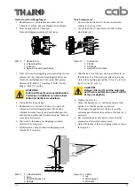
Messung am internen Aufwickler:
Die Messung des Moments erfolgt über die Bestimmung der
Zugkraft an einer direkt auf den Aufwickler befestigten
Schnur.
Der physikalische Zusammenhang zwischen Moment und
Zugkraft lautet:
M = F x r
M
= Wickelmoment
F
= Zugkraft
r
= Radius des Aufwicklers (20 mm)
Sollwerte :
M
Auf
= 22 - 24 Ncm
®
F
Auf
= 11 - 12 N
Messung und Justage :
1. Etiketten aus dem Drucker entnehmen.
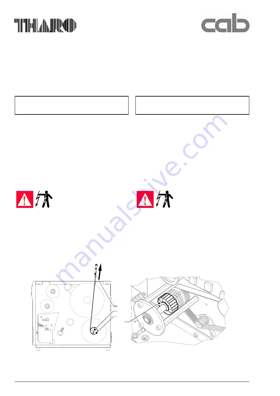
2. Schnur mit Klemmbügel (12) am internen Aufwickler
(13) befestigen und mehrfach um den Aufwickler
wickeln. Wickelrichtung beachten !
3. Federwaage (1), 25 N, an das Schnurende hängen und
senkrecht nach oben bewegen, bis sich der Wickler zu
drehen beginnt.
4. Messwert F ablesen.
Falls die Messwerte von den oben genannten Sollwerten
abweichen, führen Sie die Arbeitsschritte 5 bis 8 aus.
WARNUNG!
Lebensgefahr durch Strom-
schlag! Netzstecker ziehen!
5. Gehäuse demontieren.
6. Wickelmomente durch Drehen an der Rändelmutter
(14) justieren:
- Drehung im Uhrzeigersinn
- höheres Moment
- Drehung gegen Uhrzeigersinn - kleineres Moment
7. Messung wiederholen.
8. Nach Ende der Justage das Gehäuse montieren.
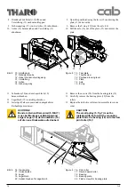
11-12 N
1
12
13
14
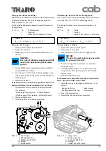
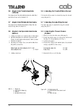
Bild 22
1 Federwaage
12 Klemmbügel
13 Interner Aufwickler
14 Rändelmutter an Kupplung
Figure 22 1 Spring scale
12 Clamp
13 Internal rewinder
14 Knurled nut at the clutch
Measuring the torque at the internal rewinder:
The torque is measured by determining the traction using a
tstring with is wound around the rewinder.
The physical relation between torque and traction is as
follows:
M = F x r
M
= torque
F
= traction
r
= radius of rewinder (0.8 in/20 mm)
Set values:
M
rewind
= 22 - 24 Ncm
®
F
rewind
= 11 - 12 N
Measure/adjust as follows:
1. Remove the labels from the printer.
2. Attach the string with the clamp (12) to the rewinder
(13) and wind the string several times around the
rewinder. Note the wind direction !
3. Attach the spring scale (1), 25 N, to the end of the
string and move it vertically upwards until the hub
starts to rotate.
5. Read the measured value F.
If the measured values differ from the set values stated
above, proceed with the steps 5 to 8.
WARNING!
Mortal danger by electric shock!
Unplug power cord!
6. Remove housing.
7. Adjust the torque by turning the knurled nut (14) as
follows:
- turning clockwise
- higher torque
- turning counterclockwise
- lower torque
8. Repeat the measurement.
9. Reassemble the housing after adjustment.

