background image

4

5

1.3 

Safety Instruction

!

Attention!

Initiation, adjustments and changing of parts is only for qualified service personal only.   

  Initiation/  Service Manual Applicators

•  Do not use the device close to high-voltage power lines.
•  Perform only those actions described in this operating manual. 

Work going beyond this may only be performed by trained personnel or service technicians.

•  Mind to a standing place with a flat and hard ground.

•  Do not load over the maximum load of 50 kg.

•  Always have service work done in a qualified workshop, where the personnel have the technical knowledge and 

tools required to do the necessary work.

•  In case of loosening the Flanged joint, secure the printer with help of a second person. 

1.4 

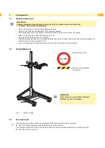
Safety Marking

1

2

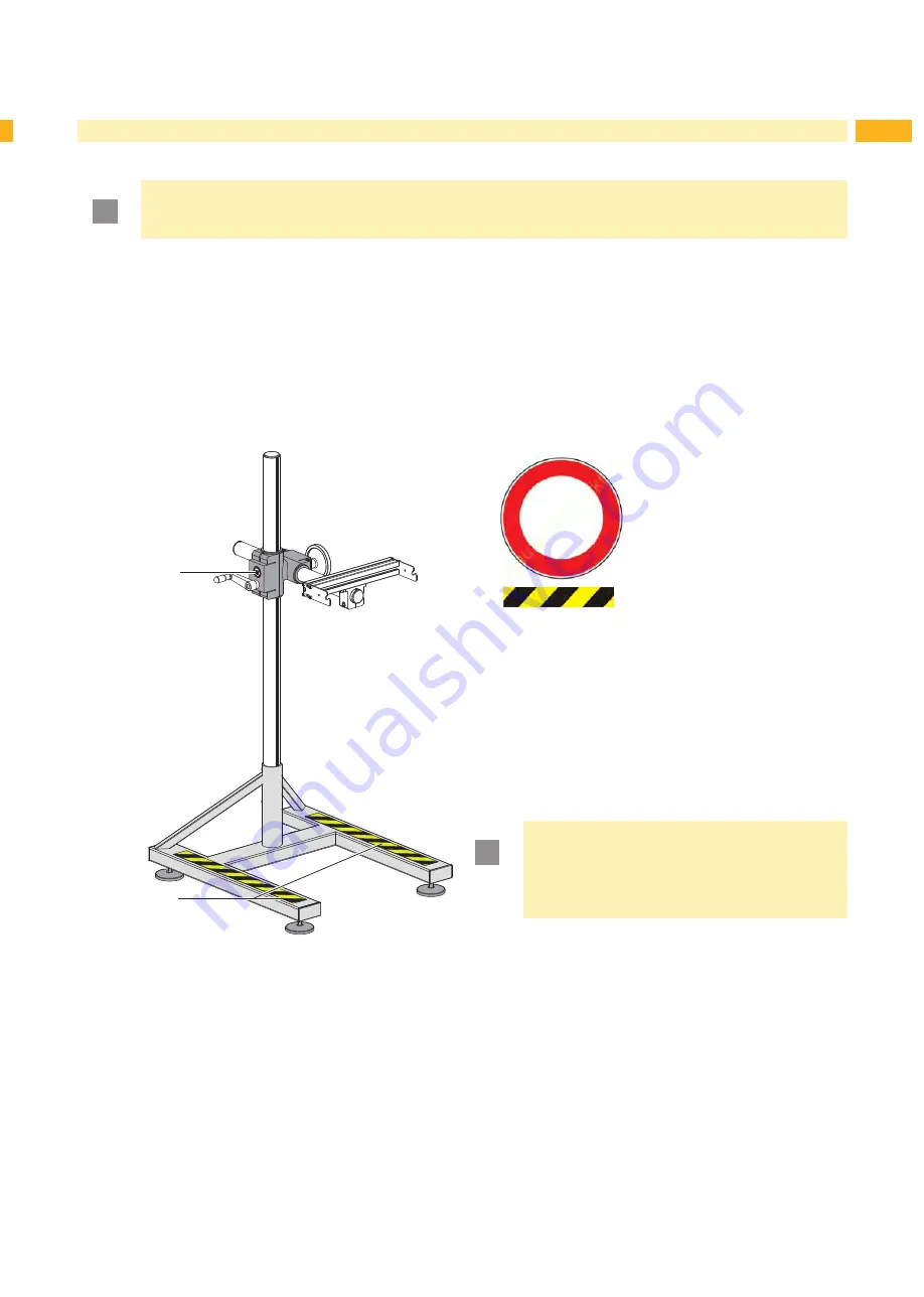
1:

max. 50kg

maximum load 50 kg

2:

Signal cover yellow/black
Trip hazard!

!

Attention!

Never remove or cover safety markings! 
Replace it in case of damage!

Fig. 1 

Safety marking

1.5 

Environment



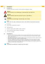
Obsolete devices contain valuable recyclable materials that should be sent for recycling.


Send to suitable collection points, separately from residual waste.

The modular construction of the print module enables it to be easily disassembled into its component parts.


Send the parts for recycling.

Introduction

Summary of Contents for Hermes+ 1602

Page 1: ...Floor Stand Operator s Manual 1602 Hermes ...

Page 2: ...ns Deliveries and performances are effected under the General conditions of sale of cab Operator s Manual for the following products Germany cab Produkttechnik GmbH Co KG Postfach 1904 D 76007 Karlsruhe Wilhelm Schickard Str 14 D 76131 Karlsruhe Telefon 49 721 6626 0 Telefax 49 721 6626 249 www cab de info cab de France cab technologies s a r l F 67350 Niedermodern Téléphone 33 388 722 501 www cab...

Page 3: ...king 5 1 5 Environment 5 2 Product Description 6 2 1 Important Features 6 2 2 Technical Data 6 2 3 Overview 7 2 4 Contents of Delivery 8 3 Mounting 9 3 1 Positional Variants 9 3 2 Mounting the Adapter Plate optional 9 3 3 Mounting of the Bracket 10 3 4 Mounting of the printer 10 4 Adjusting in Z and Y direction 11 ...

Page 4: ... 2 Intended Use The device is manufactured in accordance with the current technological status and the recognized safety rules However danger to the life and limb of the user or third parties and or damage to the device and other tangible assets can arise during use The device may only be used for its intended purpose and if it is in perfect working order and it must be used with regard to safety ...

Page 5: ... workshop where the personnel have the technical knowledge and tools required to do the necessary work In case of loosening the Flanged joint secure the printer with help of a second person 1 4 Safety Marking 1 2 1 max 50kg maximum load 50 kg 2 Signal cover yellow black Trip hazard Attention Never remove or cover safety markings Replace it in case of damage Fig 1 Safety marking 1 5 Environment Obs...

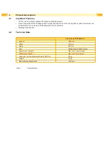
Page 6: ... can be positioned in X and Y axis to the labelling product via hand wheels Adjusting via setting feet 2 2 Technical Data Floor stand 1602 Hermes High cpl 1600 mm Width 700 mm Depth 820 mm Feet Setting feet variable in high Adjustment of height Z Gear rack crank handle Adjustment of depth Y Gear rack hand wheel Load max at a horizontal extension of 500 mm 50 kg Weight 38 kg Max labelling height ab...

Page 7: ...xle Z direction 2 Crank handle to change in Z direction 3 Joint to change the printer position 4 Hand wheel to change in Y direction 5 Flanged joint for printer mounting 6 Axle Y direction 7 Adapter plate 8 Setting feet variable 2 Product Description z y x ...

Page 8: ...ivery 1 5 6 2 1 2 3 3 2 1 2 3 3 2 3 4 1 Floor stand 2 Bracket 3 Screws M6x14 2x 4 Centering Screws 2x 5 Screws M10x50 2x 6 Adapter plate Fig 3 Contents of Delivery i Notice Please keep the original packaging in case the applicator must be returned ...

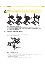
Page 9: ... positional variants to see 3 2 Mounting the Adapter Plate optional For a couple of mounting direction it s possible to mount a adapter plate It s necessary to mount it to could turn the bracket with printer and applicator 90 arround the Z axle The adapter plate is include the delivery 1 2 3 4 5 Fig 5 mounting the adapter plate 1 Loosen screws 1 and remove slot nut 5 from flanged joint 2 2 Use the...

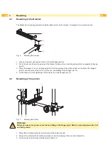
Page 10: ... of the profile is bear on the fillet of the flanged joint 3 and the holes of the slot nut 2 are over the drillings of the flanged joint 3 4 Fix the bracket 1 with tightening of the screws 4 on the flanged joint 3 3 4 Mounting of the printer 1 2 3 1 Fig 7 Mounting the printer Warning Before you mount the printer check the hard fitting of the flanged joint Mind to a standing place with a flat and h...

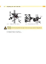
Page 11: ...ection Warning Turn the joint on the Y Axle only softly to the stopper A to fast or to strong movement can damage the axle or the joint X X Changing the height via crank handle 1 X X Changing in Y direction via hand wheel 2 4 Adjusting in Z and Y direction z y x z y x stopper ...

Page 12: ...12 12 ...

Reviews: