18
18
5
Adjustments
5.1.5 Adjusting the Stopper
i
Notice!
For operation mode "Blow on" only !
!
Attention!
Switch off the printer and close the shutoff valve for the compressed air at the service unit !
3
4
5
6
7
1
2
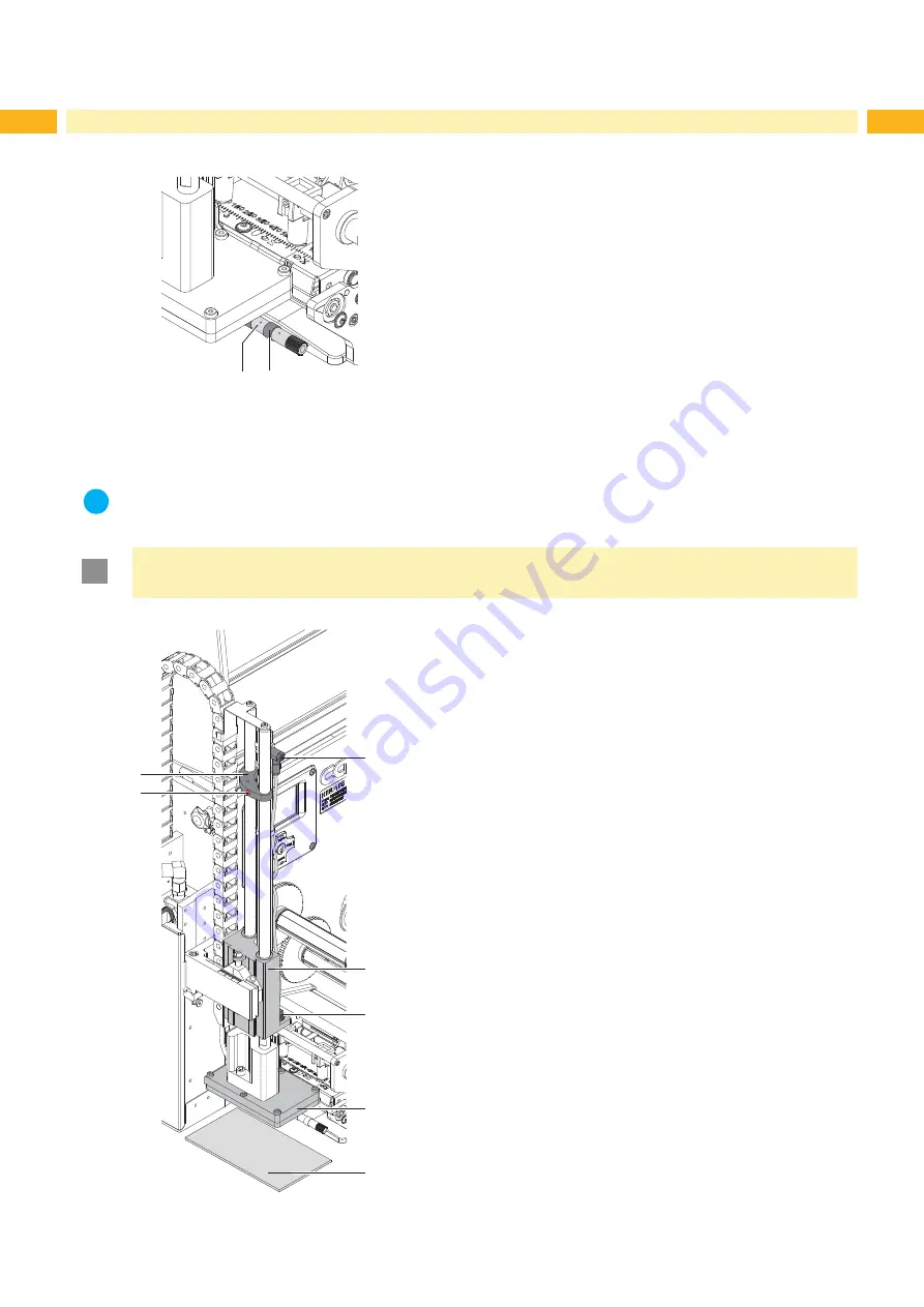
1. Place a product sample (7) at the labelling point.
2. Pull the tubes out of the push-in-fittings (3,5).
3. Loosen the screw (2) in the stopper (1).
4. Move the pad manually in the required labelling position. The
distance between the blow pad (6) in the labelling position and the
product surface (7) must not exceed 10 mm.
5. Move the stopper (1) against the guide block (4) and tighten the screw
(2).
6. Insert the tubes into the appropriate push-in-fittings (1,5).
7. Open the shutoff valve and switch on the printer.
Fig. 20
Adjusting the stopper
5.1.4 Opening the Holes on the Blow Tube
1
2
The blow tube (1) has holes for the supporting air in regular distances of
15 mm.
When the applicator is delivered only the two inner holes are open. The
other holes are closed by plastic rings (3).
To adjust the supporting air to the label width, the plastic rings (2) can be
removed from the holes.
Open all holes, which affect certainly the area of the label.
Fig. 19
Opening the holes on the blow tube


