background image

33

Block Diagram

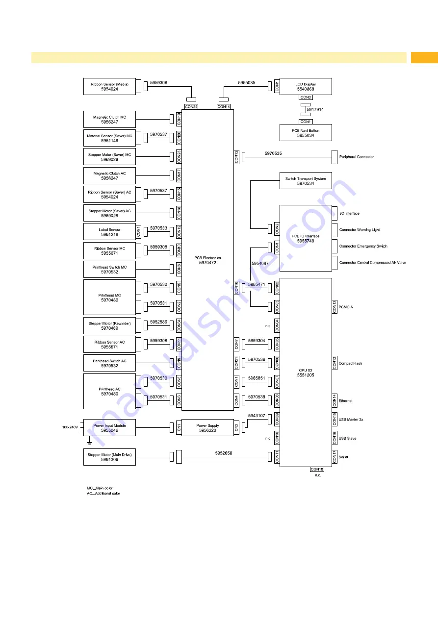
Figure 34  Block diagram Hermes C

Summary of Contents for Hermes C 6L

Page 1: ...Made in Germany Service Manual Hermes C Label Printer ...

Page 2: ... and product can occur Please check www cab de for the latest update Terms and conditions Deliveries and performances are effected under the General conditions of sale of cab Service Manual for the following products Germany cab Produkttechnik GmbH Co KG Karlsruhe Phone 49 721 6626 0 www cab de USA cab Technology Inc Chelmsford MA Phone 1 978 250 8321 www cab de us Taiwan cab Technology Co Ltd Tai...

Page 3: ...PCB CPU 16 4 8 Replacing the Power Supply Unit 17 5 Adjustments 18 5 1 Measuring and Adjusting the Winding Torques 18 5 1 1 Measuring the Winding Torques 18 5 1 2 Adjusting the Winding Torques 21 5 2 Adjusting the Brake at the Label Unwinder 22 5 3 Adjusting the Label Feed 23 5 4 Adjusting the Printing Mechanism 24 5 4 1 Preparing the Printer for Adjustment 24 5 4 2 Adjusting the Printhead Positio...

Page 4: ...ecting the environment Handling instructions Reference to chapter position picture number or document Option accessories peripherals extras Time Viewed in the display monitor 1 2 General Safety Instructions This service manual is intended for use by qualified service and maintenance personnel For more operation and configuration information refer to the user or configuration manual Follow the gene...

Page 5: ... an emergency Disconnect the current supply before carrying out the following work Installing or removing power units Working in the immediate vicinity of open power supply components Mechanical check of power supply components Modifying circuits in the device Test the zero potential of the device parts Check the working area for possible sources of danger such as wet floors defective extension ca...

Page 6: ...ber 0 1 mm cab Part No 5961064 Gauge for brake adjustment at the label unwinder cab Part No 5961092 Standard tools Screw driver Torx size TX 10 TX 20 Allen key 1 5 mm Allen key 2 5 mm 200 mm shaft included Allen key 2 5 mm included Phillips head screwdriver size 1 Snap ring pliers ZGG 0 Snap ring pliers ZGG 1 Cylindrical dynamometer spring scale 0 10 N Cylindrical dynamometer spring scale 0 25 N D...

Page 7: ...Unplug the printer from the electrical outlet and remove the rear cover 2 Remove the material from the printer 3 Unplug the connector 2 of the cable 1 from the connector of the label sensor 3 4 Loosen the screw 7 and pull the label sensor 3 with spindle 5 and the cover 6 out of the profile 4 5 Clean the label sensor 3 with a brush or a cotton swab soaked in pure alcohol 6 Move the label sensor 3 w...

Page 8: ...rinthead can be damaged by static electricity discharges and impacts X X Ground your body e g by wearing a grounded wristband X X Do not touch contacts on the plug connections 2 3 X X Do not touch printing line 5 with hard objects or your hands 6 7 8 Figure 3 Printhead replacement 1 Removing the printhead 1 Open the printhead 2 Remove labels and transfer ribbon from the printer 3 Loosen the screw ...

Page 9: ... 13 through the holes in the adjusting elements 14 and the printhead retainer 10 into the drillings 15 of the new printhead 16 2 Ensure the correct positioning of the printhead 16 at the printhead retainer 10 and tighten the screws 13 3 First connect the data cable 9 following the power cable 12 5 Push the printhead retainer 10 with the printhead onto spring 11 6 Attach the printhead retainer 10 w...

Page 10: ...terclockwise to lift the printhead assembly 2 Loosen screw 6 3 Remove ball bearing 5 and print roller 2 through the plate 3 4 Guide the new print roller through the plate 3 to the axle 1 Turn the roller easily to align it to the hexagonal end of the axle and push the roller further until it stops 5 Insert the ball bearing 5 in to the plate 3 and fix it with screw 6 4 Replacing Assembly Units ...

Page 11: ...transport rollers 1 Swing the locking system 4 away from the transport roller 2 2 Loosen the screw 3 3 Remove the transport roller 2 from the axle 1 4 Put the new roller onto the axle 1 Turn the roller easily to align it to the hexagonal end of the axle and push the roller further until it stops 5 Fix the roller 2 with the screw 3 4 Replacing Assembly Units ...

Page 12: ...and installation of the slipping clutch is also required for replacement of a winder 2 3 4 5 1 1 Coupling internal rewinder 2 Coupling ribbon rewinder additional color 3 Coupling ribbon rewinder main color 4 Brake ribbon unwinder additional color 5 Brake ribbon unwinder main color Figure 9 Slipping clutches Danger Risk of death via electric shock X X Before opening the housing cover disconnect the...

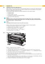
Page 13: ...1 2 1 Pin 2 Lever 3 Spring 4 Winder axle 5 Tappet 6 Brake 7 Snap ring Figure 11 Brake at the ribbon unwinder 1 Unplug the printer from the electrical outlet 2 Remove the rear cover of the printer 3 Remove the snap ring 7 4 Pull the brake 6 from the winder axle 4 Ensure that the tappet 5 remains on the winder axle Reattach the tappet to the winder axle if it has been pulled off The axle profile is ...

Page 14: ...9 remove the wall spacer 7 3 Remove the snap ring 6 4 Pull the brake shoe 5 from the pin 3 remove the spring 4 from the brake shoe 5 Insert the spring in the new brake shoe 6 Push the brake shoe onto the pin 3 in such a way that pin 2 grasps into the sink on the back side of the brake shoe and the spring 4 presses against the flap 1 of the brake lever 7 Secure the snap ring 6 8 Complete the unwind...

Page 15: ...ast one minute until the power supply unit has discharged 1 Unplug the printer from the electrical outlet and remove the rear cover 2 Remove the material from the printer 3 Disconnect the plug 2 of the cable 1 from the connector of the label sensor 3 4 Loosen the screw 7 and pull the label sensor 3 with the spindle 5 and the blind 6 out of the profile 4 5 Mount the new label sensor in the opposite...

Page 16: ...rews 2 and remove PCB CPU 1 8 Attach the new PCB CPU 1 with four screws 2 9 Connect all cables to the PCB CPU 1 10 Mount the rear cover 11 Restore all interface connections on the back of the printer 12 Connect the power cable 13 Update the firmware if necessary 14 Adjust the label sensor Configuration Manual 15 Load the printer configuration from the memory card if possible Otherwise set the prin...

Page 17: ... printer from the electrical outlet 2 Remove the rear cover 3 Dismount the PCB CPU 4 7 on page 16 4 Unplug the cables from the connectors CN1 and CN2 5 Loosen 2 screws M4x10 3 and 2 screws M4x6 2 6 Remove the power supply unit 1 7 Insert the new power supply unit an fix it with the screws 2 3 8 Connect the cable coming from the power input module to CN1 the cable Power unit CPU to CN2 9 Re mount t...

Page 18: ...s The method of measurement differs for the various types of slipping clutches Measurement of the winding torques at the transfer ribbon rewinder and unwinder page 18 Measurement of the winding torque at the internal rewinder page 20 If the winding torque differs from the set value it must be adjusted The procedures for adjusting the winding torques of the transfer ribbon winders and the internal ...

Page 19: ... 4 Attach the test collar 3 to the winder 4 5 Turn the knurled nut counterclockwise to clamp the test collar 6 Wind the cord attached to the test collar around the test collar several times 7 Secure spring scale 10 N 1 at the end of the cord 8 Move the spring scale upward vertically until the winder begins turning 9 Hold the drive belt in place during the measurement Otherwise the measurement is n...

Page 20: ...rques at the internal rewinder Danger Risk of death via electric shock X X Before opening the housing cover disconnect the device from the mains supply and wait at least one minute until the power supply unit has discharged 1 Unplug the printer from the electrical outlet 2 Remove cover 3 Remove the labels from the printer 4 Push the cord under a bracket 2 of the internal rewinder 3 and wind it aro...

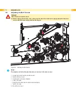
Page 21: ...least one minute until the power supply unit has discharged 2 1 Figure 19 Adjusting the winding torque 1 Unplug the printer from the electrical outlet 2 Remove the rear cover 3 Press the knurled ring 1 of the slipping clutch toward the housing wall The lock 2 of the knurled ring is released 4 Turn the knurled ring while pushing it and release it in the desired position 5 Ensure that the tabs of th...

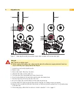
Page 22: ... the guide roller 1 touches the lower end of the slot hole 2 Figure 20 right side Requirement B In that position the brake must release the label unwinder 12 4x 11 10 6 7 8 9 13 Figure 21 Adjusting the switching point of the brake If one of the requirements will not be achieved the switching point must be re adjusted 5 Turn the knurled knob 11 clockwise and remove the margin stop 13 from the unwin...

Page 23: ...pen X X The adjustment may only be done by trained and qualified electricians X X Do not touch the power supply area Principle of adjustment Remove the rear cover Loosen the screws 12 14 Turn eccentric 9 10 Therefore the bearing plates 11 13 will be turned a little So the angles between the axles 5 8 with the pinch rollers 4 7 an the transport rollers 3 6 will be changed Tighten the screws 12 14 W...

Page 24: ...res in the order specified 1 Prepare the label printer for adjustment 5 4 1 on page 24 2 Adjust the position of the printhead 5 4 2 on page 25 3 Adjust the printhead pressure 5 4 3 on page 26 4 Adjust the transfer ribbon feed path 5 4 4 on page 27 5 Perform a final test 5 4 5 on page 27 5 4 1 Preparing the Printer for Adjustment 1 2 3 4 5 6 8 7 Figure 25 Preparing the printer for adjustment 1 Chec...

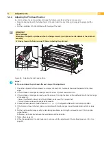
Page 25: ...izontal lines must be parallel to the label edge 2 If the printhead is not aligned properly loosen the screw 2 about one quarter turn 3 If the printhead is not aligned properly use the screws 1 to align the lines on the printhead 4 with the front edge of the slides 3 Screw 1a effects the inner half of the printhead and screw 1b the outer half Turning clockwise moves the printhead backwards 4 Creat...

Page 26: ...vel is to be reduced in the printer configuration until the print image is only barely recognizable Under these conditions inaccuracies become clearly visible during adjustment 3 Create print samples with the test function Test grid Configuration Manual or a similar print pattern 4 Adjust the adjustment screw 1a or 1b clockwise in small increments on the side with the weaker print image until the ...

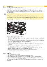
Page 27: ...d or outward turn the corresponding screw 3a or 3b clockwise in small increments Wait until the ribbon feed path has stabilized after each step of the adjustment 3 Check the ribbon feed path for wrinkles 4 If wrinkles arise on the inside turn the screw 1 counterclockwise If wrinkles arise on the outside turn the screw 1 clockwise 5 If the wrinkles cannot be remedied e g wrinkles in the center turn...

Page 28: ...e minute until the power supply unit has discharged Figure 29 Adjusting the belt tension i Notice The adjustment of all belt tension brackets can be done in the same manner 1 Unplug the printer from the electrical outlet 2 Remove the rear cover 3 Adjusting the belt tension brackets Loosen 2 screws Swing the bracket so that the belt is tensioned tightly Tighten 2 screws 4 Mount the rear cover ...

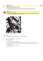
Page 29: ...te until the power supply unit has discharged 1 4 3 2 Figure 30 Adjusting the magnetic clutch i Notice The adjustment of both clutches can be done in the same manner 1 Unplug the printer from the electrical outlet 2 Remove the rear cover 3 Loosen screw 4 4 Pull armature disk 3 to the slipping clutch 5 Insert the distance caliber 0 1 mm 1 between armature disk 3 and chassis of magnetic clutch 2 6 S...

Page 30: ...3a 4 5 6 1 3b 4 5 6 Ribbon saver additional color 1 4 3a 2 5 6 3b 4 5 6 1 Figure 31 Position of eccentrics and clock wheel in the saver phase Figure 32 Position of eccentrics and clock wheel in the print phase 7 5 6 8 7 5 6 1 Unplug the printer from the electrical outlet 2 Remove the rear cover 3 Turn lever 7 clockwise to lock the printhead 4 Loosen the screws 2 at the clock wheel 5 Turn axle 1 in...

Page 31: ...rement points on the PCB CPU Figure 36 on page 35 No voltage at either measurement point The power supply unit may be defective Replace the power supply unit No voltage at one measurement point The PCB CPU may be defective Replace the PCB CPU Replace LCD Display Replace PCB Navi Button No display function but the navigator pad is functioning Replace LCD Display No navigator pad function but the di...

Page 32: ...PCB CPU VMOT Motor voltage is too low Check motor voltage 38 V at the measurement point Vmot Figure 36 on page 35 Voltage too low Replace the power supply unit Voltage is correct Replace the PCB CPU 24 V 24 V too low Check voltage at measurement point 24V Figure 36 on page 35 Voltage too low Replace the power supply unit Voltage is correct Replace the PCB CPU 24 V ext 24 V at peripheral connection...

Page 33: ...33 7 Block Diagram Figure 34 Block diagram Hermes C ...

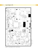
Page 34: ...34 34 8 Layout Diagram CPU Figure 35 Layout diagram PCB CPU components side ...

Page 35: ...35 Figure 36 Layout diagram PCB CPU soldering side 8 Layout Diagram CPU ...

Page 36: ...d 23 Label sensor Cleaning 7 Replacement 15 M Magnetic clutch 29 P PCB CPU Layout diagram 34 Replacement 16 Power supply unit 17 Printhead Position 25 Pressure 26 Replacement 8 Printhead position 25 Print image 24 Printing mechanism 24 Print roller 10 Protective devices 5 R Rewinder 13 19 20 Ribbon saver 30 S Safety instructions 4 Slipping clutches Adjustment 21 Replacement 12 T Test collar 18 Tor...

Reviews: