5
1.3
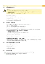
Protective Devices
!
Warning!
There is a risk of injury if protective devices are missing or defective.
Replace all protective devices (covers, safety notices, grounding cables etc) after maintenance work
has been completed.
Replace parts that have become defective or unusable.
Wear protective goggles for:
•
Knocking pins or similar parts in or out with a hammer.
•
Using spring hooks.
•
Inserting or removing springs, retaining rings or grip rings.
•
Using solvents, cleansers or other chemicals.
1.4
Handling Electricity
The following work may only be done by trained and qualified electricians:
•
Work on electrical components.
•
Work on an open device still connected to the mains supply.
General precautions before starting maintenance work:
•
Find out where the emergency and power switches are so that they can be quickly thrown in an emergency.
•
Disconnect the current supply before carrying out the following work:
- Installing or removing power units.
- Working in the immediate vicinity of open power supply components.
- Mechanical check of power supply components.
- Modifying circuits in the device.
•
Test the zero potential of the device parts.
•
Check the working area for possible sources of danger, such as wet floors, defective extension cables, defective
protective conductor connections.
Additional precautions in the case of exposed voltages:
•
Ask a second person to remain near the working site. This person must know where the emergency and power
switches are, and how to switch the current off if danger arises.
1.5
Procedure in Case of Accidents
•
Act calmly and with great care.
•
Avoid danger to yourself.
•
Switch off power.
•
Request medical assistance.
•
Give first aid, if necessary.
1.6
Environment
Obsolete assemblies contain valuable recyclable materials that should be sent for recycling.
Send to suitable collection points, separately from residual waste.
Send the parts for recycling.
Summary of Contents for Hermes C 6L
Page 1: ...Made in Germany Service Manual Hermes C Label Printer ...
Page 33: ...33 7 Block Diagram Figure 34 Block diagram Hermes C ...
Page 34: ...34 34 8 Layout Diagram CPU Figure 35 Layout diagram PCB CPU components side ...
Page 35: ...35 Figure 36 Layout diagram PCB CPU soldering side 8 Layout Diagram CPU ...


