21
5.2.3
Adjusting the Printhead Pressure
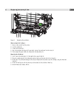
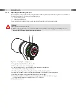
The printhead pressure can be changed with the screws (1a) and (1b) at the inside and outside of the printhead.
Increasing the printhead pressure leads to an improvement of the print image density on the corresponding side and
to a shifting of the ribbon feed path to the opposite side.
1a
1b
Figure 17
Adjusting the printhead pressure
1. Turn the adjustment screws (1a, 1b) counterclockwise until turning becomes perceptibly easy.
2. Reduce the
Heat level
in the printer configuration until the print image is only barely recognizable. Under these
conditions, inaccuracies become clearly visible during adjustment.
3. Create print samples with the test function
Test grid
(
Configuration Manual) or a similar print pattern.
4. Adjust the adjustment screw (1a or 1b) clockwise in small increments on the side with the weaker print image until
the print image is even across the entire width.
5. Set the original
Heat level
in the printer configuration.
5.2.4
Adjusting the Distance of the Printhead from the Paper Guiding Edge
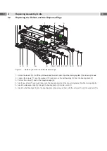
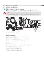
Not at PX Q with automatic ribbon saver
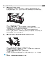
1
Figure 18
Adjusting the distance of the printhead to the paper guiding edge
The purpose of the adjustment is the positioning of the first printing dot 1 mm away from the paper guiding edge.
1.
Print labels with vertical lines at a defined X-position.
2. Measure the distance of the vertical lines from the edge of the media.
Set value: X + 1 mm.
3. If the measured value differs from the set value, shift the printhead carriage by turning the screw (1) and repeat
the measurement.
i
Note!
The screw (1) is accessible only when the printhead is closed.

