background image

29

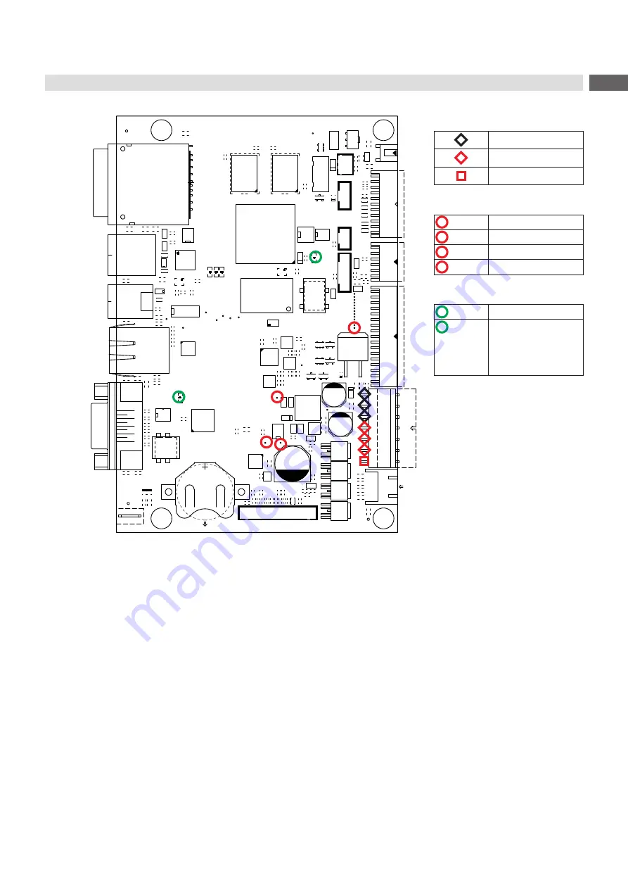
Layout Diagram PCB CPU

D4

V7

L5

C158

C159

C166

C167

C153

C154

C155

C156

C152

C161

C162

C163

C164

C160

C169

C170

C171

C172

C168

C175

C176

C177

C178

C174

C66

C112 C199

C258

C263 C265

C268

C207

C77

C157

C165

C173

C179

C206

2

4

1

3

G2

D13

V24

A

1

AE

25

E

K

B

C

D

F

G

H

J

L

M

N

P

R

T

U

V

W

Y

AA

AB

AC

AD

4

2

3

2

2

2

1

2

0

2

9

1

8

1

7

1

6

1

5

1

4

1

3

1

2

1

1

1

0

1 9 8 7 6 5 4 3 2

1

25 4

2

3

2

2

2

1

2

0

2

9

1

8

1

7

1

6

1

5

1

4

1

3

1

2

1

1

1

0

1 9 8 7 6 5 4 3 2

A

E

B

C

D

K

F

G

H

J

L

M

N

P

R

T

U

V

W

Y

AA

AB

AC

AE
AD

D1

R32

R34

R30

R1

R568

R4 R5

R19

R303

R68

R29

R96

1

1

1

R

7

9

R

R119

R120

R130

R131

R132

R61

R298

R70

R300

R268

C210

C212

C242

C15

C10

C11

C282

R62

R63

R64

R65

R73

R76

R100

R101

R270

R22

C286

L35

V14

L20

L21

L32

V2

C391

N1

62

R

32

R

V12

R33

C12

C13

L31

L34

L37

L38

C14

C16

C73

C192

C193

C194

C234

L42

R116

3

R

2

R

F2

L72

R59 R60

R84

R102

R121

R136

L26

1

N3

R150

R151

R152

R158

R159

C291

C292

U4

2

4

1

3

G6

R209

R213

R215

C246

C259

R123
R125

R71

V15

R166

1

U2

R219

R220

R160

R163

L27

R141

C219

R569 R570

R87 R88

R89

R169

V25

R171

R172

R304

R11

R21

R54

R55

L69

L70

L71

L74

L75

L83

L84

L85

R98

R99

R20

R25

R27

R36

R37

R323

V18

V19

V20

C113

F1

L30

R301

1

D14

1

D15

R254

L67

L68

C197

R117

N4

U8

R139

R227

R255

R236

R237

R280

1

#FD3

1

#FD1

1

#FD2

U3

C221

E1

R170

R168

R245

R247

R566

R567

1

Buchse

CON5

C275

A

1 2 3

7 8 9

B

C

D

E

F

G

H

J

K

L

M

N

P

R

T

D2

A

1 2 3

7 8 9

B

C

D

E

F

G

H

J

K

L

M

N

P

R

T

D3

V11

R299

C116

C148

C149

C184

R75

C187

R77

R78

C209

R85

A

1

14

B C D

E F G H J K L M N P

U7

R305

C237

C239

R155

C241

C245

X1

1bot

1top

CON3

1

CON4

R72

R74

R122

B5

B6

K

H1

K

H4

K

H5

K

H6

K

H7

C205

C255 C256

B1

B2

B3

B4

D5

P1

P2

CD

P3

P4

P5

P6

P7

P8

P9

GND

GND

WP

CON1

C307

C308

C42

R107

L29

L25

L80

L36

L43

L48

L49

L50

L1

L3

L6

L9

L10

L12

L15

L16

L17

L18

L2

L4

C260 C261

C313

C314 C320

R571

R572 R573 R574

R575

R108 R109

R294

R295

L64

R140 R142

+

C8

+

C6

R41

R42

R44

R45

V17

V1

N2

R47

R48

V3

R69

R56

R58

C267

R24

L87

L90

N6

C204

C114

2

1

CON10

2

1

CON11

2

1

CON12

1 CON17

1

CON9

1

2

CON7

1

CON16

1 CON15

1

CON14

1 CON13

+

C26

C27

C28

V9

V10

V13

V21

C288

A1

A2

K2

K1

1

Gn

Ye

CON2

1

CON8

U1

C232

C235

C240

C243

C252

V22

V23

R6

R40

1

CON18

R79

R80

V26

C196

C352

C283

C285

C3

C5

C1

C183

C180

C181

C182

C321

C150

C151

C222

C327

C4

C208

C211

C214

C215

C216

C217

C224

C223

C198C200

C201

C202

C203

C72

C9

C264

C272

C276
C279

C280

C269

C335

C338

C339

C340

C341

C293

C324

C342

C343 C344

C290 C295

C296

C297

C287

C299

C185

C186

C278

C300

C303

C301

C277

C270

C230

C231

C322

C323

C225

C325

C220

C302

C304

C271

C309

C310

C311

C312

C345

C346

C347

C349

C350

C2

C262 C266

C213

C289

C298

R126

R134

R137

R253

R256

R31

R35

L13

L93

L24

L28

L14

L23

L51

L52

L39

L66

L56

L57

L58

L40 L89

L59

L60

L61

L62

L63

L73

L53

C273

L33

R13

L7
L8

L11
L22

L91

L92

TOP4

TOP2

TOP3

TOP1

TOP26

TOP10

TOP9

TOP8

TOP25

TOP5

TOP6

TOP17

TOP18

TOP19

TOP20

TOP21

TOP22

TOP14

TOP13

TOP15

TOP16

TOP24

TOP23

TOP7

TOP12

TOP11

Measuring points at CON9:

GND

+24V

+V

MOT 

(+24V)

Measuring points on the PCB:

 TOP2

+24V

 TOP3

+5V

 TOP25

+24V TPH

 TOP26

+V

MOT 

(+24V)

LEDs on the PCB:

 H1

+3,3V

 H7

LED FPGA
on during start 
procedure 
blinking after start 
procedure

Figure 25 

Layout diagram PCB CPU X4.3

Summary of Contents for PX Q4.3L

Page 1: ...Service Manual PX Q MADE IN GERMANY Print Module...

Page 2: ...r development of our products discrepancies between documentation and product can occur Please check www cab de for the latest update Terms and conditions Deliveries and performances are effected unde...

Page 3: ...asuring and Adjusting the Winding Torques 16 5 1 1 Measuring the Winding Torques 16 5 1 2 Adjusting the Winding Torques 18 5 2 Adjusting the Printing Mechanism 19 5 2 1 Preparing the Printer for Adjus...

Page 4: ...ction Reference to section position illustration number or document Option accessories peripheral equipment special fittings Time Information in the display 1 2 General Safety Instructions This servic...

Page 5: ...ng power units Working in the immediate vicinity of open power supply components Mechanical check of power supply components Modifying circuits in the device Test the zero potential of the device part...

Page 6: ...Cylindrical dynamometer spring scale 0 10 N Digital circuit analyzer 2 2 Removing and Installing the Rear Cover Attention The rear cover or cables can be damaged via careless handling X Move cable out...

Page 7: ...scharged 1 Unplug the device from the electrical outlet and remove the rear cover 2 Remove the material from the printer 3 Disconnect the cable 4 from the connector 5 of the label sensor 3 4 Loosen th...

Page 8: ...lution 1 2 3 4 3 4 5 1 Data connector 2 Power connector 3 Threaded holes 4 Catching holes 5 Heating line Figure 3 Structure of the printhead Attention The printhead can be damaged by static electricit...

Page 9: ...rst unplug the power cable 8 followed by the data cable 7 Mounting the Printhead 1 First connect the data cable 7 followed by the power cable 8 2 Place the printhead into the printhead assembly and in...

Page 10: ...stem 8 and swing it down 2 Loosen the screws 11 and the washers 10 and remove the ball bearings 9 from the bearing plate 2 3 Pull out the rollers 7 and or the dispense edge 6 4 Insert new rollers 7 an...

Page 11: ...gure 6 Slipping clutches Preparation Danger Risk of death via electric shock X Before opening the rear cover disconnect the device from the mains supply and wait at lease one minute until the power su...

Page 12: ...without automatic ribbon saver PX Q with automatic ribbon saver Figure 8 Brake at the ribbon unwinder 1 PX QR Lift the electronics unit page 11 2 Remove the snap ring 7 3 Pull the brake 6 from the win...

Page 13: ...sensor Removing the label sensor 1 Unplug the device from the electrical outlet and remove the rear cover 2 Remove the material from the printer 3 Disconnect the cable 4 from the connector 5 of the l...

Page 14: ...n Manual 2 Unplug the printer from the electrical outlet 3 Detach all interface cables from the back of the printer 4 Remove all memory media from the slots 5 Dismount the rear cover 6 Unplug all plug...

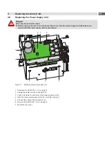
Page 15: ...inute until the power supply unit has discharged 1 1 2 1 3 1 1 1 Figure 11 Replacing the power supply unit 1 Dismount the PCB CPU 4 5 on page 14 2 Unplug the cable from the connectors 3 3 Loosen 6 scr...

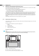
Page 16: ...e coupling torque and the torque of the brake Only the torque of the brake is measured when the winding axis is rotating in the winding direction For this reason measurements of the torques at the rew...

Page 17: ...il the power supply unit has discharged 1 Unplug the printer from the electrical outlet 2 Remove the rear cover 2 2 on page 6 3 Remove the transfer ribbon from the printer 4 Attach the test collar 3 t...

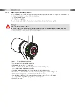
Page 18: ...minute until the power supply unit has discharged 2 1 Figure 14 Adjusting the winding torque 1 Unplug the printer from the electrical outlet 2 Remove the rear cover 2 2 on page 6 3 Press the knurled...

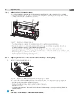
Page 19: ...ns Adjustment of the printing mechanism comprises the following procedures in the order specified 1 Preparing the printer for adjustment 5 2 1 on page 19 2 Aligning the printhead to the print roller 5...

Page 20: ...of damage Attempting to adjust the printhead when the fixing screws 1 are tight can lead to defects at the printhead assembly X Always loosen the fixing screws 1 before adjusting the printhead i Note...

Page 21: ...figuration Manual or a similar print pattern 4 Adjust the adjustment screw 1a or 1b clockwise in small increments on the side with the weaker print image until the print image is even across the entir...

Page 22: ...lear resistance when turning the adjustment screw 4 you may only continue turning the screw in very small increments but no more than one eighth of a turn X Only turn the adjustment screw 4 as far as...

Page 23: ...Unplug the printer from the electrical outlet 2 Remove the rear cover 2 2 on page 6 3 Loosen screw 3 of the belt tension bracket 2 to adjust the tension of belt 5 between motor and print roller 4 4 Sw...

Page 24: ...m the mains supply and wait at lease one minute until the power supply unit has discharged 1 3 2 4 Figure 21 Adjusting the head switches 1 Unplug the printer from the electrical outlet 2 Remove the re...

Page 25: ...PX QL PX QR Figure 22 Checking the eccentrics position 1 Remove the label material 2 Lock the printhead 3 Switch on the printer The ribbon saver will be synchronized After this the eccentrics are in...

Page 26: ...ply and wait at lease one minute until the power supply unit has discharged 4 2 3 1 Figure 23 Adjusting the magnetic clutch 1 Unplug the printer from the electrical outlet 2 Remove the rear cover 3 Lo...

Page 27: ...ter and computer match For an Ethernet connection check the validity of the IP address and the subnet mask Check the interface cable and replace it if necessary If all functionality of the interface h...

Page 28: ...28 28 7 Block Diagram Figure 24 Block diagram PX Q...

Page 29: ...R85 A 1 14 B C D E F G H J K L M N P U7 R305 C237 C239 R155 C241 C245 X1 1bot 1top CON3 1 CON4 R72 R74 R122 B5 B6 K H1 K H4 K H5 K H6 K H7 C205 C255 C256 B1 B2 B3 B4 D5 P1 P2 CD P3 P4 P5 P6 P7 P8 P9 G...

Page 30: ...acement 13 M Magnetic clutch 26 Motor 23 P PCB CPU 29 PCB CPU replacement 14 Power supply replacement 15 Printhead position 20 Printhead pressure adjustment 21 Printhead replacement 8 Print image 19 R...

Reviews: