14
14
4.1.3
Setting the Label Sensor
1 2 3 4
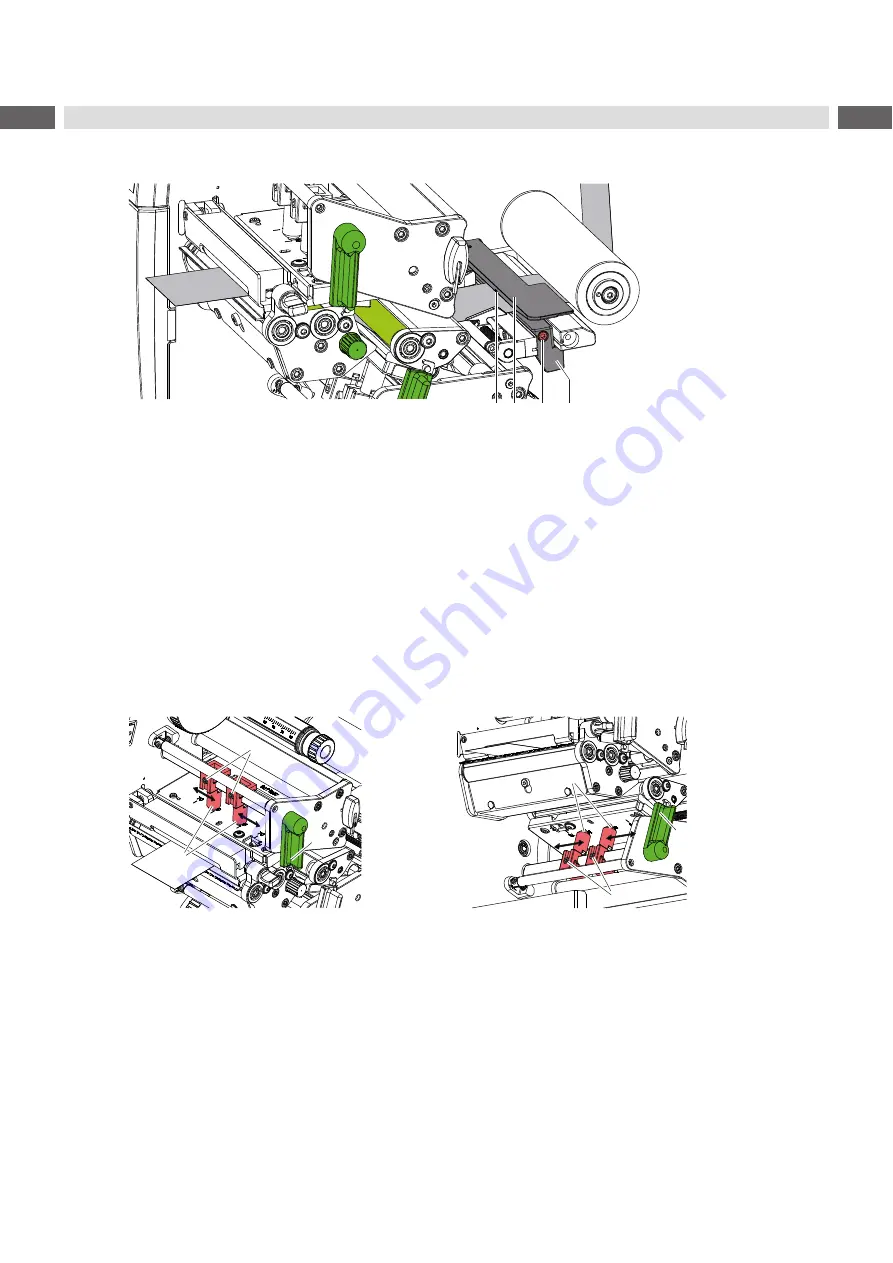
Figure 14 Setting the label sensor
The label sensor can be shifted perpendicular to the direction of paper flow for adaptation to the media. The sensor
unit (2) of the label sensor is marked with an indentation in the label sensor retainer. When the printer is switched on,
a yellow LED illuminates the sensor position.
Loosen screw (3).
Position label sensor with tab (4) in such a way that the sensor (1) can detect the label gap or a reflex or perfo
-
ration mark.
- or, if the labels deviate from a rectangular shape, -
Align label sensor using the tab (4) with the front edge of the label in the direction of paper flow.
Tighten screw (3).
4.1.4
Setting the Head Locking Systems
1
2
3
1
2
4
Figure 15
Setting the upper head locking system
Figure 16 Setting the lower head locking system
The printheads are pushed on via two plungers (1). In the basic setting the plungers are set in the middle of the
printhead retainer. This setting can be used for the most applications.
If the print density decreases in the outer areas when using very large media, the plungers can be displaced :
1. Turn lever (3) clockwise and the lever (4) counterclockwise to lock the printheads.
2. Loosen threaded pins (2) at the plungers (1) with Allen key.
3. Displace plungers symmetrically as necessary maximal to the scale value 70.
4. Tighten the threaded pins (2).


