MP800 UHD Media Player Manual
Page
41
of
45
Rev. 100- 10/17/16
General Purpose Input/Output (GPIO) Options
The MP800 may be ordered with a GPIO interface board to allow pushbuttons to trigger actions on the media player.
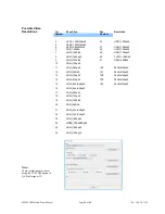
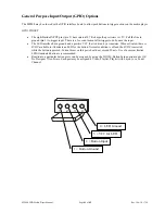
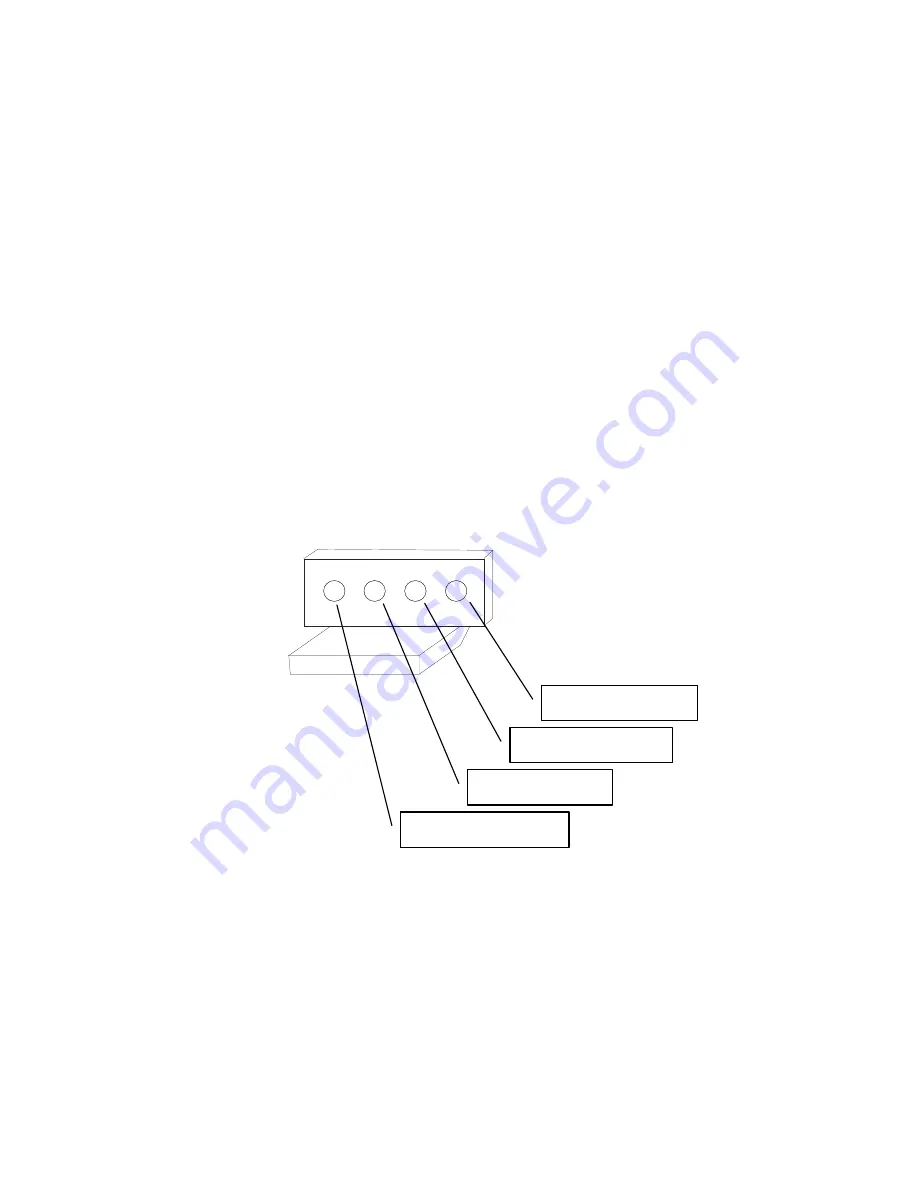
GPIO PINOUT
The eight Button INPUT pins (pin 2) have internal 4.7 K ohm pull-up resistors to +5V. Pull the line to
ground (pin 1) to trigger input. There is a 3 second lockout after trigger to de-bounce the input.
The LED interface has a ground and a positive VCC that is driven by a transistor. When activated, there is
4VDC available to illuminate an LED for the button. Normal condition is off and the 4VDC is asserted
while the button is pressed. Current draw on this port should not exceed 20 mA. Use of a current limited
LED illuminated button is recommended.
Reaction to a particular button press can be assigned by using the TOOLS, Button Setup option in our QS
Pro Designer 7X software. Each port may be assigned a Video, Playlist, Playlist with Layout, or a Tuner
Channel.
1 = Button Ground
1 2 3 4
2 = Button Input
3 = VCC for LED
+
4 = LED Ground
-


