background image

Chapter 4: Generic Attribute Registration Protocol (GARP)

4-6

Local Management Supplement

GVRP Protocol


(Toggle)

Enables or disables the GVRP Protocol on the switch.

When set to Enable, all port settings are valid for GVRP enabling those 
ports to send/receive frames to other GVRP-aware switches. Disable 
makes the port settings invalid.

The default setting is “Disable”.

To enable or disable the protocol, refer to 

Section 4.3.2

.

4.3.1

Setting a Port to Operate in GMRP or GVRP

To set a port to be a GMRP or GVRP aware port. Proceed as follows:

1.

Use the arrow keys to highlight the GMRP or GVRP field of the port.

2.

Press the SPACE bar to choose (yes).

3.

Repeat steps 1 and 2 to set GMRP and GVRP of ports as necessary.

4.

Use the arrow keys to highlight the SAVE command. 

5.

Press ENTER. The message “SAVED OK” displays and all settings 
are saved. 

4.3.2

Setting All Ports on the Switch

All ports on the switch can be set at one time to one mode of operation 
using the Set All Ports field.

To select the mode of operation using the Set All Ports field, proceed as 
follows:

1.

Use the arrow keys to highlight the Set All Ports field 

2.

Press the SPACE bar to select one of the following: 

GMRP Enable All 

GMRP Disable All 

GVRP Enable All 

GVRP Disable All 

Enable All

Disable All 
Summary of Contents for 2E43-51R

Page 1: ...9032971 01 SmartSwitch Series 2E42 2E43 2E48 2E49 2H22 2H23 2H28 2H33 and 2M46 Local Management Supplement...

Page 2: ......

Page 3: ...GES WHATSOEVER INCLUDING BUT NOT LIMITED TO LOST PROFITS ARISING OUT OF OR RELATED TO THIS MANUAL OR THE INFORMATION CONTAINED IN IT EVEN IF CABLETRON SYSTEMS HAS BEEN ADVISED OF KNOWN OR SHOULD HAVE...

Page 4: ...ly the one 1 copy of the Program provided in this package subject to the terms and conditions of this License Agreement You may not copy reproduce or transmit any part of the Program except as permitt...

Page 5: ...computer software submitted with restricted rights in accordance with section 52 227 19 a through d of the Commercial Computer Software Restricted Rights Clause and its successors and iii in all resp...

Page 6: ...the right to use only the one 1 copy of the Program provided in this package subject to the terms and conditions of this License Agreement You may not copy reproduce or transmit any part of the Progra...

Page 7: ...computer software submitted with restricted rights in accordance with section 52 227 19 a through d of the Commercial Computer Software Restricted Rights Clause and its successors and iii in all respe...

Page 8: ...ou have the right to use only the one 1 copy of the Program provided in this package subject to the terms and conditions of this License Agreement You may not copy reproduce or transmit any part of th...

Page 9: ...computer software submitted with restricted rights in accordance with section 52 227 19 a through d of the Commercial Computer Software Restricted Rights Clause and its successors and iii in all resp...

Page 10: ...55022 EN 50082 1 EN 60950 Equipment Type Environment Networking Equipment for use in a Commercial or Light Industrial Environment We the undersigned hereby declare under our sole responsibility that...

Page 11: ...u Screen 1 19 1 9 High Speed Interface Configuration Screen 1 21 1 9 1 Configuring an FE 100FX or FE 100F3 1 23 1 9 2 Setting the FE 100FX or FE 100F3 Operational Mode 1 24 1 9 3 Configuring an FE 100...

Page 12: ...Default Priority of a Port 1 58 CHAPTER 2 LM SECURITY SCREENS FOR 2E43 51 2E43 51R DEVICES 2 1 Repeater Configuration Menu Screen 2 1 2 2 Repeater Level Security Configuration 2 2 2 2 1 Setting the Re...

Page 13: ...peration Status Screen 4 4 4 3 1 Setting a Port to Operate in GMRP or GVRP 4 6 4 3 2 Setting All Ports on the Switch 4 6 4 4 GMRP Configuration Screen 4 7 4 4 1 Setting a Mode Port by Port 4 8 4 4 2 S...

Page 14: ......

Page 15: ...ppression Configuration Screen 1 35 1 15 802 1 Configuration Menu Screen 1 38 1 16 Switch Configuration Screen 1 40 1 17 802 1Q VLAN Screen Hierarchy 1 43 1 18 802 1Q VLAN Configuration Menu Screen 1...

Page 16: ...ng Default Values 1 55 1 3 TX Priority Regeneration Default Values 1 56 2 1 ENET Repeater Port Relationship 2 6 3 1 CONN Repeater Port Relationship 3 3 3 2 CONN Network Organization 3 4 3 3 CONN Repea...

Page 17: ...devices with firmware revisions through 4 09 xx and documents the changes and additions affecting the 802 1Q VLAN User s Guide and the SmartSwitch user s guides listed in Table 1 1 Table 1 1 User s G...

Page 18: ...LAN Cabletron Systems SecureFast switching A separate image is required for this operation Depending on the Operational Mode set for the device the hierarchy of the Local Management screens differs as...

Page 19: ...on Configuration Ethernet Full Duplex Configuration High Speed Interface Configuration Fast Ethernet Interfaces HSIM SmartTrunk Configuration Port Redirect Configuration Redirect Configuration Menu Po...

Page 20: ...Status Advanced Port Priority Configuration Port Priority Configuration 802 1p Priority Configuration Menu GMRP Group Registrations GMRP Configuration Port Redirect Configuration Redirect Configurati...

Page 21: ...14 BOOTPROM Revision XX XX XX MAC Address IP Address Subnet Mask Default Gateway TFTP Gateway IP Addr Device Date Device Time Screen Refresh Time Screen Lockout Time Clear NVRAM NO Device Uptime XX D...

Page 22: ...ays Figure 1 4 Device Configuration Menu Screen The following briefly explains each screen accessible from the Device Configuration Menu screen GENERAL CONFIGURATION Used to monitor and configure Smar...

Page 23: ...ch utilization and the peak switch utilization For details refer to Section 1 4 FLASH DOWNLOAD CONFIGURATION Used to force the SmartSwitch to download a new image file from a TFTP server to its FLASH...

Page 24: ...eys to highlight the SYSTEM RESOURCES INFORMATION menu item and press ENTER The System Resources Information screen displays Figure 1 5 System Resources Information Screen The following briefly define...

Page 25: ...switching capacity used since the last reset Reset Peak Switch Utilization Toggle Used to reset the Peak Switch Utilization field The switch may be set to either YES or NO as described in Section 1 4...

Page 26: ...Configuration screen displays Figure 1 6 Flash Download Configuration Screen NOTE The user may also force the download of an image by changing the position of dipswitch 6 located inside the device Ref...

Page 27: ...when user chooses RUNTIME This field notifies the user that the SmartSwitch device will reboot after the download is complete If a RUNTIME Download is performed this field toggles between YES and NO I...

Page 28: ...P Addr field 4 Set the IP address of the TFTP gateway server this defaults to the same IP address as that set in the TFTP Gateway IP Addr field on the General Configuration screen 5 Use the arrow keys...

Page 29: ...eys to highlight the TFTP Gateway IP Addr field 6 Set the IP address of the TFTP gateway server this defaults to the same IP address as that set in the TFTP Gateway IP Addr field on the General Config...

Page 30: ...in the General Configuration screen 5 Use the arrow keys to highlight EXECUTE at the bottom of the screen and press ENTER The message BOOTP DOWNLOAD WILL COMMIT TO FLASH REBOOT IN PROGRESS displays in...

Page 31: ...E CONFIGURATION The High Speed Interface Configuration screen provides access to the Fast Ethernet Interfaces screen and the HSIM screen For details refer to Section 1 8 SMARTTRUNK CONFIGURATION Used...

Page 32: ...urity Configuration screens In the 2H23 50R and 2H33 37R devices the screens are the Repeater Configuration Menu screen and its two subordinate screens Repeater Level Security Configuration and Port L...

Page 33: ...time To set Ethernet ports for Standard operation refer to Section 1 7 1 FULL DUPLEX Depending on the SmartSwitch the port transmits and receives data simultaneously at 10 or 100 Mbps thus enabling th...

Page 34: ...To set ports refer to Section 1 7 1 1 12 13 24 25 36 or 37 48 Navigation Key When the Full Duplex Configuration screen displays the current operation mode and status information are displayed for the...

Page 35: ...r until you see FULL or STANDARD 3 Use the arrow keys to highlight the SAVE command on the bottom line of the screen 4 Press ENTER The message SAVED OK displays 1 8 HIGH SPEED INTERFACE CONFIGURATION...

Page 36: ...lowing briefly explains each screen accessible from the High Speed Interface Configuration Menu screen FAST ETHERNET INTERFACES Displays the types of fast Ethernet interfaces installed in the device t...

Page 37: ...e Configuration Menu screen use the arrow keys to highlight the FAST ETHERNET INTERFACES menu item and press ENTER The High Speed Interface Configuration screen displays Figure 1 10 High Speed Interfa...

Page 38: ...a link signal present and a valid physical connection to another device No Link There is no link signal present and no valid physical connection to another device Current Oper Mode Read only This fiel...

Page 39: ...full duplex mode In normal operation with all capabilities enabled the FE 100TX advertises that it has the ability to operate in any mode The Network Manager or user may choose to set up the port so...

Page 40: ...In normal operation an FE 100TX interface automatically establishes a link with the device at the other end of the segment and no user setup is required Section 1 9 4 and Section 1 9 5 provide instruc...

Page 41: ...r modes This field steps to 10Base T 10Base TFD full duplex 100Base TX and 100Base TXFD full duplex To set the advertised ability proceed as follows 1 Use the arrow keys to highlight the Desired Oper...

Page 42: ...IRECT CONFIGURATION menu item and press ENTER The Redirect Configuration Menu screen displays Figure 1 11 Redirect Configuration Menu Screen The following defines each selectable item of the Redirect...

Page 43: ...with port 2 as the destination port Frames from port 1 are then automatically redirected to port 2 according to the configured frame format and frames with errors can be either forwarded or dropped a...

Page 44: ...en The following definitions briefly explain each field of the Port Redirect Configuration screen Source Port Read Only Shows which ports are currently set as source ports Destination Port Read Only S...

Page 45: ...format setting Source Port n Selectable Used to select the port n that is to be changed to a source port If a port is currently being redirected it will not display as a selectable port For details r...

Page 46: ...5 Use the arrow keys to highlight the Frame Format field near the bottom of the screen 6 Use the SPACE bar or BACKSPACE to step to the appropriate frame format setting NORMAL TAGGED or UNTAGGED for t...

Page 47: ...be forwarded in the frame format as received tagged or untagged The VLAN redirect function is very useful for troubleshooting purposes It allows traffic associated with a particular VLAN to be sent to...

Page 48: ...of the VLAN Redirect Configuration screen Source VLAN Read Only Shows the VLAN ID of the VLANs that are currently set as source VLANs Destination Port Read Only Shows which ports are currently set as...

Page 49: ...VLAN that is to be changed to a source VLAN If a VLAN is currently being redirected it will not display as a selectable VLAN For details refer to Section 1 11 1 Destination Port n Selectable Used to s...

Page 50: ...the appropriate frame format setting RECEIVED TAGGED or UNTAGGED for the selected Destination Port 7 Use the arrow keys to highlight the Status field 8 Use the SPACE bar to select either the ADD or D...

Page 51: ...CAST SUPPRESSION CONFIGURATION menu item and press ENTER The Broadcast Suppression Configuration screen displays Figure 1 14 Broadcast Suppression Configuration Screen NOTE Broadcast frames received a...

Page 52: ...receive broadcast frames that will be forwarded per port per second For details on how to set the threshold refer to Section 1 13 1 Reset Peak Toggle Used to reset the Peak Rate Resetting the Peak Ra...

Page 53: ...AVE command at the bottom of the screen 4 Press ENTER The message SAVED OK displays and the Time Since Peak field is also reset 1 14 REPEATER CONFIGURATION MENU SCREENS The Repeater Configuration Menu...

Page 54: ...ONFIGURATION MENU item and press ENTER The 802 1 Configuration Menu screen displays Figure 1 15 802 1 Configuration Menu Screen The following briefly describes each screen that is accessible from the...

Page 55: ...tch and set each port to operate as a GVRP or GMRP aware port so it can send receive frames from other GVRP or GMRP aware devices GVRP and GMRP enables the switch to dynamically create VLANs and Multi...

Page 56: ...ead Only Displays the total number of switched ports on the SmartSwitch device Type of STA Toggle Allows the user to set the method that the switches use to decide which switch is the controlling Root...

Page 57: ...anagement disabled this interface No traffic is received or forwarded while the interface is disabled Listening The switch is not adding information to the Transparent Database The switch is monitorin...

Page 58: ...TA setting allows the user to set the method that the switches use to decide which is the controller Root switch when two or more switches are in parallel The available selections are IEEE DEC and NON...

Page 59: ...been added to the SmartSwitch device to enable the operation of IGMP on selected VLANs A switch supporting 802 1Q VLANs provides the VLAN Configuration screens as a standard part of its Local Managem...

Page 60: ...able or disable VLANs within the device and also associate the VLANs to a Filter Database ID FID It also enables the user to configure attributes that apply to the entire switch and or VLANs Refer to...

Page 61: ...s associated with a specific VLAN ID and protocol type Refer to your SmartSwitch device user s guide for additional information IGMP VLAN CONFIGURATION Used to enable or disable IGMP Internet Group Ma...

Page 62: ...3 For additional information about IGMP refer to Appendix A To access the IGMP VLAN Configuration screen from the Layer 3 Extensions Menu screen use the arrow keys to highlight the IGMP VLAN CONFIGURA...

Page 63: ...P Query Interval Modifiable If the switch is the querier the value in the Query Interval field indicates how often IGMP Host Query frames are transmitted on the VLAN selected in the VLAN ID field This...

Page 64: ...Queries sent in response to the Leave Group messages and is also the amount of time between Group Specific Query messages This value may be tuned to modify the leave latency of the network A reduced v...

Page 65: ...NS Toggle New VLANs can be set up by default to be either ENABLED or DISABLED A VLAN is set up by choosing the number for that VLAN 1 19 1 Configuring VLANs for IGMP To set up IGMP protocol for VLANs...

Page 66: ...riority Multicast Configuration Menu screen Figure 1 20 provides access to the Port Priority Configuration and Advanced Port Priority Configuration screens These screens are used for the following Set...

Page 67: ...each port for frames that are received without priority information in their tag header For details refer to Section 1 21 ADVANCED PORT PRIORITY CONFIGURATION Used to map priorities to transmit queue...

Page 68: ...ty 5 A frame with priority information in its tag header is transmitted according to that priority To access the Port Priority Configuration screen from the Priority Multicast Configuration Menu scree...

Page 69: ...value of 0 through 7 with 0 being the lowest priority and 7 the highest can be selected that will apply to all ports To set the default transmit priority for all ports refer to Section 1 21 2 1 21 1...

Page 70: ...h a priority 1 then those frames would be transmitted before any frames with a priority that has the TX queue set to 0 Priority Regeneration is used to classify different types of traffic by repriorit...

Page 71: ...o one of two TX queues 0 or 1 with 0 being the lowest transmit level Refer to Table 1 2 for the TX Queue default values according to frame priority To set the TX Mapping Queues refer to Section 1 22 1...

Page 72: ...es with an RX priority of 3 could be regenerated with a TX priority of 5 The new value would also be inserted in the VLAN tag if the frame is tagged as outbound The regenerated priority is used to det...

Page 73: ...n is the lowest level TX queue 6 If more than one TX queue is to be changed repeat steps 4 and 5 until all the appropriate TX queue settings are changed 7 Use the arrow keys to highlight the SAVE comm...

Page 74: ...Port To set the default port priority proceed as follows 1 Use the arrow keys to highlight the Port field 2 Type in the number of the port having the default priority changed 3 Use the arrow keys to...

Page 75: ...ATION MENU SCREEN The Repeater Configuration Menu screen Figure 2 1 is used to access the Repeater Level Security Configuration or Port Level Security Configuration screen To access the Repeater Confi...

Page 76: ...For details refer to Section 2 3 2 2 REPEATER LEVEL SECURITY CONFIGURATION The Repeater Level Security Configuration screen Figure 2 2 is used to set the state of security according to connector All p...

Page 77: ...ollows NonSecure Allows the ports on the connector to receive all frames The source address of received frames is not examined and the frames are processed in a non secure state LockedOnAddr The Secur...

Page 78: ...ction On Intruder field Action On Intruder Toggle Used to select the actions taken for the selected security state There are two fields in which to select the actions Both toggle to activate or deacti...

Page 79: ...VED OK displays and all ports of the connector are set to the selected operating mode 2 3 PORT LEVEL SECURITY CONFIGURATION SCREEN The Port Level Security Configuration screen Figure 2 3 functions sim...

Page 80: ...frames The source address of received frames is not examined and the frames are processed in a non secure state The last source address detected is displayed in the address column This provides a qui...

Page 81: ...on an address and the frame received violates the set security the actions selected in the Action On Intruder field are executed Action On Intruder Toggle Used to select the actions taken for the sel...

Page 82: ...t or LockedOnAddr 6 If the security level chosen causes the DisablePort and SendTrap fields to display under Action On Intruder use the arrow keys to highlight the DisablePort field If the security le...

Page 83: ...9 13 Use the arrow keys to highlight the SAVE command 14 Press ENTER The message SAVED OK displays and all ports of the connector are set to the selected operating mode 15 To change the security on a...

Page 84: ...Chapter 2 LM Security Screens for 2E43 51 2E43 51R Devices 2 10 Local Management Supplement...

Page 85: ...peater Configuration Menu screen Figure 3 1 is used to access the Repeater Port Configuration Module Level Security Configuration or Port Level Security Configuration screen To access the Repeater Con...

Page 86: ...of the next frame received LockOn Next or lock on the address of the last frame received Locked On Addr For details refer to Section 3 3 PORT LEVEL SECURITY CONFIGURATION Used to set the security for...

Page 87: ...r ports 13 24 CONN 2 Repeater ports 13 24 CONN 3 Repeater ports 25 36 CONN 3 Repeater ports 25 36 CONN 4 Repeater ports 37 48 PORT NETWORK LINK STAT CURRENT OPER MODE DESIRED OPER MODE PORT STAT 1 1 N...

Page 88: ...Neg is selected the port automatically negotiates with the device to which it is attached to determine its Operating Mode 10 Mbps or 100 Mbps When 10Base T is selected the port is forced to operate i...

Page 89: ...ight the CONNECTOR field 2 Use the SPACE bar to step to the appropriate connector number 3 Press ENTER to display the repeater port settings on that connector 4 Use the arrow keys to highlight the DES...

Page 90: ...e simultaneously using the SET ALL PORTS field as follows 1 Use the arrow keys to highlight the CONNECTOR field 2 Use the SPACE bar to step to the appropriate connector number 3 Press ENTER to display...

Page 91: ...n either of the last two options are set the switch can be set to enable or disable the reception of frames and send or not send traps when an intruder is detected To access the Module Level Security...

Page 92: ...nnector to receive all frames The source address of received frames is not examined and the frames are processed in a non secure state LockOnNext The next frame received by each port is examined to le...

Page 93: ...o select the actions taken for the selected security state There are two fields to select the actions Both toggle to activate or deactivate the action DisablePort NoDisable DisablePort causes the swit...

Page 94: ...isplays and all ports of the connector are set to the selected operating mode 3 4 PORT LEVEL SECURITY CONFIGURATION SCREEN The Port Level Security Configuration screen Figure 3 4 is used to set the se...

Page 95: ...the changed state Table 3 4 CONN Repeater Port Relationship 2H23 50R 2H33 37R CONN 1 Repeater ports 1 12 CONN 1 Repeater ports 1 12 CONN 2 Repeater ports 13 24 CONN 2 Repeater ports 13 24 CONN 3 Repea...

Page 96: ...received with that same source address are allowed on that port All frames received that do not have that same source address will cause the device to execute the actions selected in the Action On Int...

Page 97: ...MAC address for the LockedOnAddr security state setting Once a secure address is defined on a port only those frames received with that same source address are allowed on that port Any other frame det...

Page 98: ...To change the DisablePort setting to NoDisable press the SPACE bar to toggle the setting 8 Use the arrow keys to highlight the SendTrap field 9 To change the setting to NoTrap press the SPACE bar to...

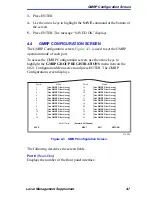
Page 99: ...scribes the GMRP Configuration screen and how to use it to select individual ports or all of the ports and apply one of four modes of operation according to or regardless of the multicast address regi...

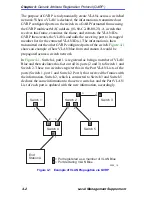
Page 100: ...re 4 1 shows an example of how VLAN blue from end station A would be propagated across a switch network In Figure 4 1 Switch 4 port 1 is registered as being a member of VLAN Blue and then declares thi...

Page 101: ...es on ports The GMRP uses the multicast address 01 80 C2 00 00 20 for controlling the flooding of multicast frames End stations register with the port that they are connected to and tell the port whic...

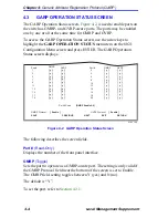
Page 102: ...creen displays Figure 4 2 GARP Operation Status Screen The following describes the screen fields Port Read Only Displays the number of the front panel interface GMRP Toggle Sets the port to operate as...

Page 103: ...ets all ports as not GMRP aware ports All ports are set to N under GMRP GVRP Enable All Sets all ports as GVRP aware ports All ports are set to Y under GVRP GVRP Disable All Sets all ports as not GVRP...
Page 104: ...ollows 1 Use the arrow keys to highlight the GMRP or GVRP field of the port 2 Press the SPACE bar to choose Y yes 3 Repeat steps 1 and 2 to set GMRP and GVRP of ports as necessary 4 Use the arrow keys...

Page 105: ...ing describes the screen fields Port Read Only Displays the number of the front panel interface 2762 34 RETURN EXIT Port 1 2 3 4 5 6 7 8 9 10 11 12 Mode Use GMRP Filter Unreg Use GMRP Filter Unreg Use...

Page 106: ...address The default setting for this field is Use GMRP Filter Unreg For details on selecting a mode refer to Section 4 4 1 Set All Ports Selectable This field enables all ports to be set to one mode s...

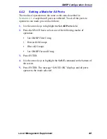
Page 107: ...erate in one mode proceed as follows 1 Use the arrow keys to highlight the Set All Ports field 2 Press the SPACE bar to select one of the following modes of operation Use GMRP Filter Unreg Forward All...

Page 108: ......

Page 109: ...ss and manage network devices Figure 5 1 shows the updated Network Tools Help screen To access the Network Tools screen access Local Management then use the arrow keys to highlight the NETWORK TOOLS m...

Page 110: ...ER For detailed information see the applicable Local Management User s Guide 5 1 1 Built in Command The built in command listed in this section activates a new function on the managed module being acc...

Page 111: ...network devices and establish the topology of the network fabric This protocol can also be used by the SmartSwitch device to propagate specific information to neighboring network devices The user may...

Page 112: ......

Page 113: ...ceive it IGMP queries are sent periodically from routers An end station that will receive a multicast stream will send a query response back to the router If the router does not receive any response f...

Page 114: ...host requesting to receive queries The frame is an IP frame of protocol type 2 If the frame is a response frame IGMP will take the multicast address and VLAN ID and program a filter on the receive por...

Page 115: ...F is IP protocol type 0x59 To detect that the frame is a multicast OSPF MOSPF the OSPF data must be looked at The data starts after the IP header Byte 31 options needs to be checked If bit 2 is set 0x...

Page 116: ......

Page 117: ...on screen 2Hxx action on intruder 3 9 connector 3 8 security state 3 8 E Ethernet Full Duplex Configuration screen link status 1 18 operation mode 1 17 port status 1 18 port 1 17 set all ports 1 18 F...

Page 118: ...creen destination port 1 29 source port 1 29 VLAN Redirect Configuration screen destination port 1 33 source VLAN 1 33 Network Tools 5 1 built in commands cdp 5 3 O Operating Mode On Repeater Ports 2H...

Page 119: ...reen 4 7 hierarchy of 1 2 High Speed Interface Configuration Menu screen 1 19 High Speed Interface Configuration screen 1 21 IGMP VLAN Configuration screen 1 45 Password screen 1 2 Port Level Security...

Page 120: ...on 1 9 DRAM installed 1 9 FLASH memory installed 1 8 NVRAM installed 1 9 peak switch utilization 1 9 reset peak switch utilization 1 9 T Table formats A 1 Transmit queues mapping of 1 57 TX priorities...

Reviews: