Chapter 5: Diagnostics and Troubleshooting
Page 5-4
Ethernet Switch Module User Guide
During a remote loopback test, the port is in normal operation, sending
and receiving packets to its network. The ATX generates loopback
packets which are sent out of the port to a particular destination device on
the port’s network. The destination device echoes the packet back onto the
network, and the originating port receives the packet.
For both types of tests, normal operation is indicated when generated
packets are received back (after looping) without errors. For remote
loopback tests, the ATX creates LLC Type 1 test packets for LANs and
PPP echo-request packets for WANs and UARTs.
Both types of loopback tests can be initiated by the NMS, and test results
are reported to the NMS.
5.2.1
Diagnostic Results
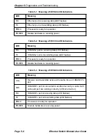
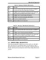
ATX diagnostic results are indicated in two ways: by observing the front
panel LEDs (which are explained later in this chapter) or by reading NMS
trap messages. Both power-up and loopback diagnostics produce traps,
which are sent to the NMS and may be logged for future reference. In
some cases it may be more convenient to simply observe the LEDs, but in
most cases traps provide more information. There are no LEDs for the
loopback tests—the results of these tests must be observed (i.e., accurate
packet transmission) or read using an NMS (i.e., examine traps).
5.3 TROUBLESHOOTING
5.3.1
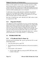
If The Module Fails To Power Up
If the Ethernet Switch Module fails to power up when the ATX is on and
functioning properly:
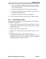
1. Check the status of ports using LCM.
2. Reset the Ethernet Switch Module and observe the power-up sequence
again.
3. If the sequence is still abnormal:
a.
Take the module offline by pressing the OFFLINE button on the
module’s front panel.
Summary of Contents for 3E02-04
Page 2: ......
Page 30: ...Chapter 4 Monitoring Page 4 4 Ethernet Switch Module User Guide ...
Page 36: ...Chapter 5 Diagnostics and Troubleshooting Page 5 6 Ethernet Switch Module User Guide ...
Page 40: ...Chapter 6 Adding Swapping Modules Page 6 4 Ethernet Switch Module User Guide ...
Page 44: ...Appendix A Technical Specifications Page A 4 Ethernet Switch Module User Guide ...
Page 52: ...Appendix B Cables Page B 8 Ethernet Switch Module User Guide ...
Page 54: ...Index Index 2 Ethernet Switch Module User Guide ...


