Troubleshooting
Ethernet Switch Module User Guide
Page 5-5
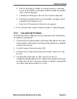
b. Remove the interface module by unscrewing the two retaining
screws on the module’s front panel. Pull the module out using the
“ears” on the front panel.
c.
Carefully but firmly press down on all socketed components.
d. Re-install the module. Make sure the module is properly seated
and tighten the retaining screws.
e.
Reset the ATX and observe the power-up sequence.
4. If it is still abnormal, contact Cabletron Systems Technical Support.
5.3.2
Connectivity Problems
If the Ethernet Switch Module powers up normally but the workstations
are unable to communicate:
1. Check the LEDs for abnormalities which may help indicate the source
of the problem. (LED behavior during normal operation is explained
earlier in this chapter.)
2. Check the status of the ports using LCM.
3. Check for loose connections between the module, transceivers, and
devices.
4. Check that the proper type of cable is used: crossover or
straight-through depending on the configuration; distance limitations
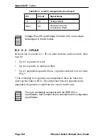
are adhered to; the 5-4-3 rule is not violated, etc. (Refer to Appendix B
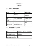
for cabling information and the 5-4-3 rule.)
Summary of Contents for 3E02-04
Page 2: ......
Page 30: ...Chapter 4 Monitoring Page 4 4 Ethernet Switch Module User Guide ...
Page 36: ...Chapter 5 Diagnostics and Troubleshooting Page 5 6 Ethernet Switch Module User Guide ...
Page 40: ...Chapter 6 Adding Swapping Modules Page 6 4 Ethernet Switch Module User Guide ...
Page 44: ...Appendix A Technical Specifications Page A 4 Ethernet Switch Module User Guide ...
Page 52: ...Appendix B Cables Page B 8 Ethernet Switch Module User Guide ...
Page 54: ...Index Index 2 Ethernet Switch Module User Guide ...


