Chapter 2: Connecting to the Network
FDDI Dual-Attached Intelligent Module User’s Guide
Page 2-13
You can use a MIC A plug and the FDDI MIC A receptacle instead of
MIC B, in which case the equivalent RING A LEDs will be on.
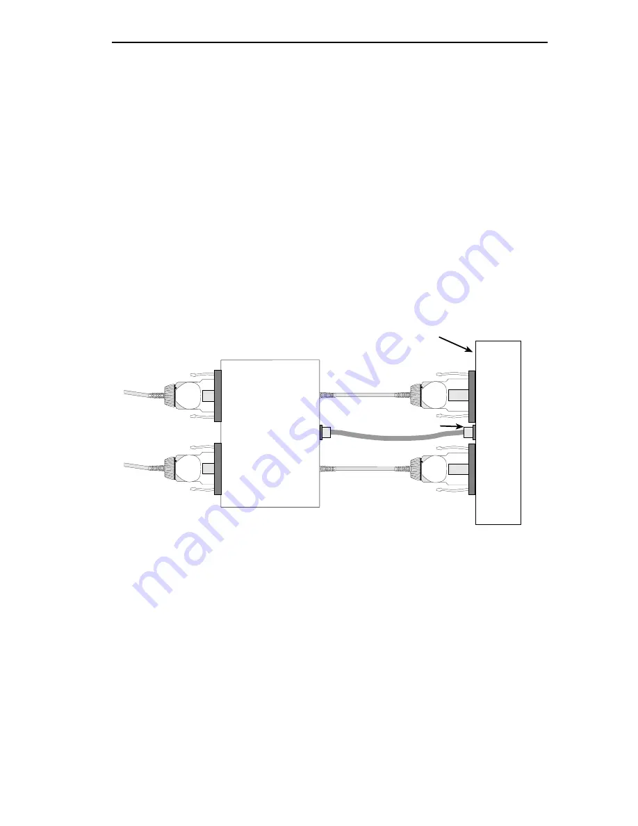
2.4.5 Connecting the Optical Bypass Switch
The OBS has three built-in cables with MIC A and MIC B plugs and a
male RJ-11 connector for connecting to the 3F00-01 or 3F55-01. It also
contains MIC A and MIC B receptacles for connecting to the ring.
Figure 2-9 shows the OBS connectors.
You also need two cable assemblies consisting of a fiber cable appropriate
to the type of cabling you are using (either multimode or single mode)
with a MIC A plug on one end and a MIC B plug on the other end to
connect the OBS to the ring.
Figure 2-9
Connecting the Optical Bypass Switch
1. Attach the MIC A and MIC B plugs on the OBS to the receptacles
labeled “FDDI MIC A” and “FDDI MIC B” respectively on the
module front panel.
2. Plug the male RJ-11 connector on the OBS into the female RJ-11
connector on the module front panel.
3. Attach the MIC A plug on the end of the first cable assembly to the
MIC A receptacle on the OBS (Figure 2-9).
MIC A
MIC B
MIC B
MIC A
Optical
Bypass
Switch
RJ11 Connector
ATX
3F00-01 Front Panel
Summary of Contents for 3F00-01
Page 2: ......
Page 10: ...Contents viii FDDI Dual Attached Intelligent Module User s Guide ...
Page 62: ...Chapter 6 Adding Swapping Modules Page 6 4 FDDI Dual Attached Intelligent Module User s Guide ...
Page 66: ...Appendix A Technical Specifications Page A 4 FDDI Dual Attached Intelligent User s Guide ...
Page 68: ...Appendix B Cabling Information Page B 2 FDDI Dual Attached Intelligent Module User Guide ...


