background image


903number


SmartSwitch 9000

9F426-03

User’s Guide

Summary of Contents for 9F426-03

Page 1: ...903number SmartSwitch 9000 9F426 03 User s Guide...

Page 2: ......

Page 3: ...ABLE FOR ANY INCIDENTAL INDIRECT SPECIAL OR CONSEQUENTIAL DAMAGES WHATSOEVER INCLUDING BUT NOT LIMITED TO LOST PROFITS ARISING OUT OF OR RELATED TO THIS MANUAL OR THE INFORMATION CONTAINED IN IT EVEN...

Page 4: ...se harmful interference to radio communications Operation of this equipment in a residential area is likely to cause interference in which case the user will be required to correct the interference at...

Page 5: ...in the Radio Interference Regulations of the Canadian Department of Communications Le pr sent appareil num rique n met pas de bruits radio lectriques d passant les limites applicables aux appareils nu...

Page 6: ...checks or adjustments The output is factory set and does not allow any user adjustment Class 1 Laser transceivers comply with the following safety standards 21 CFR 1040 10 and 1040 11 U S Department...

Page 7: ...or 55 x 10 6 watts Removing the optical connector from the transceiver allows laser radiation to emit directly from the optical port The maximum radiance from the optical port under worst case conditi...

Page 8: ...pment for use in a Commercial or Light Industrial Environment We the undersigned hereby declare under our sole responsibility that the equipment packaged with this notice conforms to the above directi...

Page 9: ...SmartSwitch 9000 Chassis 2 5 The Reset Switch 2 7 Chapter 3 Operation System Management Buses 3 1 SMB 1 Bus 3 2 SMB 10 Bus 3 2 System Diagnostic Controller 3 2 DC DC Converter 3 2 INB Interface 3 3 S...

Page 10: ...Contents viii Appendix A FPIM Specifications FPIM 00 and FPIM 01 A 1 FPIM 02 and FPIM 04 A 2 FPIM 05 and FPIM 07 A 3...

Page 11: ...bus is 64 bits wide with a bandwidth of 320 Mbps Since all frame translation address lookups and forwarding decisions are performed in hardware the 9F426 03 can obtain a throughput performance of grea...

Page 12: ...ee front panel FDDI interfaces The front panel connections are via standard Cabletron FPIMs Management Information Base MIB Support Both 9F426 03 provides MIB support including IETF FDDI MIB IETF MIB...

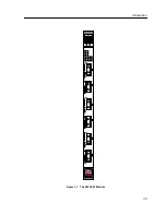
Page 13: ...1 3 Introduction Figure 1 1 The 9F426 03 Module SMB CPU INB 9F426 03 FDDI...

Page 14: ...ems service contract number A description of the failure A description of any action s already taken to resolve the problem e g changing mode switches rebooting the unit etc The serial and revision nu...

Page 15: ...bag Observe all precautions to prevent damage from Electrostatic Discharge ESD 3 Carefully examine the module checking for damage If any damage exists DO NOT install the module Contact Cabletron Syst...

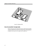
Page 16: ...nts Figure 2 2 shows the various components that are accessible to the user These consist of an eight position DIP switch explained below replaceable PROMs and sockets for RAM These will be used for f...

Page 17: ...r Accessible Components An eight position DIP switch is located on the module card as shown in Figure 2 2 The function of the switches are listed in Table 2 1 SMB 1 PROM Boot PROM Flash SIMM Socket 1...

Page 18: ...in NVRAM when the module is powered down and remain there until the switch is toggled again 6 Force BootP Download Toggling this switch after pulling the board out of the SmartSwitch 9000 clears down...

Page 19: ...nto the ESD Wrist Strap Grounding receptacle in the lower right corner of the SmartSwitch 9000 chassis shown in Figure 2 3 3 Grasp the module and slide it into the slot Make sure that the module s cir...

Page 20: ...Installing the 9F426 03 Module Metal Back Panel Module Guides Module Jack for ESD Wrist Strap Plastic Tab Warning Ensure that the circuit card is between the card guides Lock down the top and bottom...

Page 21: ...power down the module and or restart the module To reset the module s i960 processor press the reset switch twice within three seconds To shutdown the module press and hold the reset switch for three...

Page 22: ...Installing the SmartSwitch 9000 Module 2 8...

Page 23: ...nical format The SmartSwitch ASIC circuitry decides from header information where the packets should be sent They are then converted from canonical format to the proper format for that interface Figur...

Page 24: ...the SMB 10 bus periodically send out loop back packets to ensure the validity of SMB 10 In the event a fault is detected on the SMB 10 the SMB 1 can be used as an alternate communication channel by th...

Page 25: ...he host processor the INB backplane and LAN WAN interfaces on the front panel of SmartSwitch 9000 modules The SmartSwitch ASIC can operate in two modes Traditional Switch When operating in traditional...

Page 26: ...ributed LAN Monitor telnet and network address to MAC address mapping are also provided by the i960 core The Host engine sends and receives packets via the CPU SmartSwitch ASIC Interface This allows t...

Page 27: ...the status of the module and may be used as an aid in troubleshooting Shown in Figure 4 1 is the LANVIEW LEDs of the 9F426 03 module Figure 4 1 The LANVIEW LEDs SMB CPU INB 9F426 03 FDDI INB Transmit...

Page 28: ...llow Testing Power up Testing Yellow Flashing Crippled Not fully operational i e one bad port Yellow Green Booting Blinks yellow and green while booting Red Reset Normal power up reset Red Flashing Fa...

Page 29: ...ont panel port The A and B LEDs indicate the status of the A and B ports The P and S LEDs indicate the status of the primary and secondary FDDI rings The FDDI Status LEDs are shown in Figure 4 2 Figur...

Page 30: ...n Ports Enabled and PCM Active Green Green Off Green THRU A Green Off Green Green THRU B Green Green Yellow Yellow WRAP A Yellow Green Yellow Green WRAP B Green Green Yellow Green WRAP AB Green Red Re...

Page 31: ...cations Technical Specifications CPU Intel i960 RISC based microprocessor Memory 4 Meg Flash Memory expandable to 32 Meg 16 Meg DRAM Standards ANSI FDDI X3T9 5 SMT MAC PHY MMF PMD SMF PMD Network Inte...

Page 32: ...ice MTBF MHBK 217E 200 000 hrs MTTR 0 5 hr Physical Dimensions 35 0 D x 44 0 H x 3 0 W centimeters 13 8 D x 17 4 H x 1 2 W inches Weight Unit 1 36 kg 3lb Shipping 1 81 kg 4lb Environment Operating Tem...

Page 33: ...2 1 FPIM 00 and FPIM 01 The FPIM 00 and FPIM 01 provide a multimode fiber connection The FPIM 00 uses a MIC style connector and the FPIM 01 uses an SC type connector The specifications for both devic...

Page 34: ...The pinouts for both are listed in Table A 3 The link distance is up to 100 meters on unshielded twisted pair cable as specified by ANSI TP PMD Table A 2 Transmitter Power Parameters Parameter Typica...

Page 35: ...Table A 4 The link distance is up to 40 kilometers max and 25 kilometers typical on single mode fiber optic cable as specified by ANSI SMF PMD Table A 4 FPIM 05 and FPIM 07 Specifications Parameter T...

Page 36: ...FPIM Specifications A 4...

Reviews: