background image

Central Site Remote Access Switch     243

C

ONFIGURING

 A

LTERNATE

 A

CCESSES

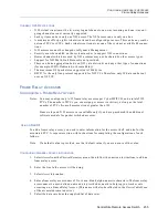
Dedicated Accesses

D

EDICATED

 A

CCESS

 C

ONFIGURATION

 E

LEMENTS

L

INES

The line that will be used for the dedicated access. A dedicated access can be defined on either a 
BRI, a PRI, a network V.35, or a network RS232 line.

B

EARER

 C

HANNELS


For BRI and PRI lines only. Also referred to as B channels. B channels can carry voice or data in 
either direction. 

C

LOCKING

 T

YPE


For V.35 and RS232 lines only. Clocking types can be either external or internal. Dedicated 
connections usually use external clocking.

L

INE

 P

ROTOCOL

Designates the type of line protocol that will be used on the dedicated connection. PPP line protocol 
is the correct selection for most configurations. HDLC protocol may work for devices that only 
support HDLC protocol. 

D

EVICE

 N

AME

 (O

PTIONAL

Optional parameter. The device name of the device assigned to this dedicated connection. The 
device name may be up to 17 characters in length, and is case sensitive. If you configure this 
parameter, and, in addition, turn off outbound authentication for this device, no authentication will 
be needed for this particular device. If you do not configure this parameter, device authorization is 
required for the device.

D

EDICATED

 A

CCESS

 B

ACKGROUND

 I

NFORMATION

To access dedicated network connections, there must be a physical connection between the 
network and the CyberSWITCH. The dedicated access defines how the CyberSWITCH will use this 
physical connection.

The dedicated connection is used in addition to any switched connections that can be made to 
provide overflow data capacity to the remote device. The dedicated connection is brought up at 
initialization time. The Throughput Monitor starts monitoring the dedicated connection for an 
overload condition. When link utilization causes an overload condition, additional switched 
connections will be made to the remote device based on the data rate configured for that device. 
When the link utilization causes an underload condition, the switched connections will be released 
with the dedicated connection remaining active.

Switched connections can also be used to provide backup connectivity to the remote device in case 
the dedicated connection fails. If the dedicated connection goes down, and there is network traffic, 
switched connections will be made to the remote device based on the data rate configured for that 
device thus providing backup for the dedicated connection. When the dedicated connection comes 
back up, it will be aggregated together with any switched connections that may be active.

When the link utilization causes an underload condition, the switched connections will be released 
with the dedicated connection remaining active.

Device level authentication must be enabled for dedicated accesses to properly identify the remote 
device and provide switched backup and overflow to that device.

Summary of Contents for Cabletron CyberSWITCH CSX5500

Page 1: ...CENTRAL SITE REMOTE ACCESS SWITCH USER S GUIDE Release 7 4 Cabletron Systems 603 332 9400 phone 603 337 3075 fax support ctron com...

Page 2: ...ED TO THIS MANUAL OR THE INFORMATION CONTAINED IN IT EVEN IF CABLETRON SYSTEMS HAS BEEN ADVISED OF KNOWN OR SHOULD HAVE KNOWN THE POSSIBILITY OF SUCH DAMAGES Copyright 1999 by Cabletron Systems Inc Al...

Page 3: ...ics 1993 including one or more U S Patents No 4701745 5016009 5126739 and 5146221 and other pending patents Telenetworks Copyright 1991 92 93 by Telenetworks All rights reserved FCC NOTICE This device...

Page 4: ...ontrol Council for Interference by Information Technology Equipment VCCI If this equipment is used in a domestic environment radio disturbance may arise When such trouble occurs the user may be requir...

Page 5: ...atform Description 42 Cleaning the CSX5500 Air Filter 43 Platform Characteristics 44 Caution for DC Powered CSX5500s 45 The CSX6000 46 Platform Description 46 Cleaning the CSX6000 Air Filter 47 Platfo...

Page 6: ...7 The DM 8 68 The DM 24 68 The DM 24 and DM 30 68 Encryption Adapter 69 Software Overview 70 System software 70 Administration software 70 System Files 71 Configuration Files 71 Operational Files 72 U...

Page 7: ...dapter Inter Board Cables 94 Connecting Multiple Adapters 94 Connecting a WAN Adapter to the LCD 96 Summary of Guidelines 97 Cabling Guidelines 97 Termination Guidelines 97 Accessing the CyberSWITCH 9...

Page 8: ...rce 119 Configuring a Line for V 35 and RS232 Resources 120 Configuring Changes for a COMMPORT Resource 121 Line Configuration Elements 122 Line Background Information 126 R2 Signaling 127 Subaddresse...

Page 9: ...RIP Background Information 159 SECURITY AND ENCRYPTION OPTIONS 160 Security Overview 161 Overview 161 Security Level 161 System Options and Information 162 Device Level Databases 162 User Level Datab...

Page 10: ...evice Entries 184 Configuring On node Device Entries 184 On node Device Database Configuration Elements 191 General Configuration Elements 191 ISDN Configuration Elements 191 Frame Relay Access Config...

Page 11: ...TACACS Authentication Server 218 Configuring a TACACS Authentication Server 218 TACACS Authentication Server Configuration Elements 219 TACACS Authentication Server Background Information 219 ACE Auth...

Page 12: ...a Dedicated Access 242 Dedicated Access Configuration Elements 243 Dedicated Access Background Information 243 X 25 Accesses 244 Configuring an X 25 Access 244 Basic Configuration Information 244 LAPB...

Page 13: ...73 Bridge Filter Definitions 274 Dial Out Using Bridge Filters 283 Example Bridge Dial Out Using a Destination MAC Address Filter 283 Known Connect List 285 Configuring the Known Connect List 285 Usin...

Page 14: ...DHCP Relay Agent 308 Configuring a DHCP Relay Agent 308 DHCP Configuration Elements 309 DHCP Background Information 309 DHCP BOOTP Relay Agent Environments 309 Example DHCP Configurations 311 DHCP Pr...

Page 15: ...nfiguration Elements 336 IPX NetWare Static Services Background Information 337 IPX Spoofing 337 Configuring IPX Spoofing 337 IPX Spoofing Configuration Elements 338 IPX Spoofing Background Informatio...

Page 16: ...outes Background Information 363 AppleTalk Capacities 363 Configuring AppleTalk Capacities 363 AppleTalk Capacities Configuration Elements 363 AppleTalk Capacities Background Information 364 AppleTalk...

Page 17: ...385 Configuring D Channel Callback 385 D Channel Callback Configuration Elements 386 D Channel Callback Background Information 386 Digital Modem Inactivity Timeout 387 Configuring the Digital Modem In...

Page 18: ...d CCP 412 TFTP 414 Configuring TFTP 414 TFTP Configuration Elements 414 TFTP Background Information 414 File Attributes 415 Configuring File Attributes 415 File Attributes Configuration Elements 415 F...

Page 19: ...Interface 445 IPX 446 IPX Router Initialized 446 IPX Routing Operational 447 IPX Routing over a LAN Connection 447 IPX Remote LAN Connection 448 IPX Routing over a WAN Connection 450 Triggered RIP SA...

Page 20: ...r Messages 481 System Message Summary 482 Trace Messages 544 Overview 544 Call Trace Messages 545 Call Trace Message Summary 546 IP Filters Trace Messages 551 PPP Packet Trace Messages 552 WAN FR_IETF...

Page 21: ...roughput Information 582 Throughput Monitor Contents 583 Saving Operational Information 584 Clearing Operational Information 584 Configuration Related Commands 585 Terminating and Restarting the Cyber...

Page 22: ...Statistics 632 AppleTalk Transaction Protocol ATP Statistics 632 AppleTalk Port Statistics 633 Bridge Statistics 634 Call Detail Recording Statistics 634 Compression Statistics 635 Compression Related...

Page 23: ...WAN Statistics 660 X 25 Statistics 661 X 25 Access Related Statistics 661 X 25 Virtual Circuit VC Related Statistics 663 Routine Maintenance 665 Overview 665 Installing Upgrading System Software 665 E...

Page 24: ...Information 688 Bridging 688 IP Routing 688 IPX Routing 689 AppleTalk Routing 690 CFGEDIT Map 691 Overview 691 Main Menu 691 Physical Resources Menu 692 Options Menu 693 Security Menu 696 Getting Assi...

Page 25: ...ral different types of databases either locally or on a variety of remote databases System security also allows the configuration of administrative session Telnet session enhancements This provides se...

Page 26: ...odes may appear in call trace messages SYSTEM ADAPTERS Provides illustrations of available adapters for the CyberSWITCH DOCUMENTATION SET This guide the User s Guide provides information to install an...

Page 27: ...letron com support relnotes When you initially install or upgrade your system an abbreviated version of these notes are available for display Or after the system is operating you may display them by i...

Page 28: ...berSWITCH DOCUMENTATION TITLES All references to CyberSWITCH documentation titles will use the same font as normal text but will be italicized For example all references to the User s Guide will appea...

Page 29: ...rSWITCH network We include an overview of unique system features interoperability security interfaces system components remote devices and switches supported Hardware Overview A description of system...

Page 30: ...applications such as telecommuting electronic mail multi media transmission imaging and CAD Devices dial up into a single system using a multi line hunt group to extend the capabilities offered by an...

Page 31: ...stomer defined filters can forward messages based on addresses protocol or packet data Combining Leased Line and Switched Connections Use the Switched Connections feature to automatically backup faile...

Page 32: ...o support a number of modems on a single board from eight V 34 modems to thirty K56Flex modems depending upon adapter model The digital modem feature conforms to the V 90 standard Dynamic Management M...

Page 33: ...ecludes one of the CyberSWITCH nodes from properly performing its function it will order the other CyberSWITCH node to take over the other s duties by taking on its identity i e its MAC and IP address...

Page 34: ...connections to multiple locations These locations can connect by using different channels on the same line or they can connect on different lines This pooling of lines among many potential locations...

Page 35: ...MAC layer bridges connect to the system using the HDLC bridge encapsulation line protocol These devices send transparently bridged Ethernet frames to the system MAC layer bridges do not process netwo...

Page 36: ...y are encrypted and encapsulated The destination address on the encapsulated datagram is that of the CyberSWITCH node servicing the other trusted subnet When the IP datagram reaches the destination Cy...

Page 37: ...TACACS or ACE server programmed for use with security token cards With user level security the potential network user explicitly connects to the server and must properly converse with it in order to c...

Page 38: ...work 100 1 1 0 SYSTEM COMPONENTS The major components of the CyberSWITCH are System hardware consisting of a platform an administration port provided by the platform and adapters System software speci...

Page 39: ...ate ISDN port The basic rate port is connected to the switched digital network and is used to make connections to the CyberSWITCH The Ethernet port is used to connect to a remote LAN The remote bridge...

Page 40: ...ity Yes Yes AT T Legend Yes NA NET3 Yes NA NET5 NA Yes NT DMS 100 Yes Yes NT DMS 250 NA Yes NT DMS 500 NA Yes NT SL 100 Yes Yes NTT Yes Yes NI 1 Yes NA TS013 Yes NA TS014 NA Yes 1TR6 Yes Yes Country S...

Page 41: ...uced by Network Express SYSTEM PLATFORMS The CyberSWITCH consists of a main processor and system memory The type of processor and the number of available slots vary by model See table The front of the...

Page 42: ...m cards V 35 Frame Relay and Dedicated Lines services It supports TCP IP IPX and AppleTalk as well as ML PPP and compression It has single or dual port Ethernet capability The CSX5500 utilizes a CPU w...

Page 43: ...ust behind the left side of the chassis front panel For best performance and as an alternative to replacement regularly wash the filter in warm water and a mild detergent Before removing the air filte...

Page 44: ...HARACTERISTICS Physical Characteristics Height 171 5 mm 6 86 in Width 430 mm 17 2 in Depth 483 mm 19 32 in Weight 18 kg maximum 40 lb maximum Environmental Characteristics Operating Temp 0 to 55 C 32...

Page 45: ...circuit overcurrent protection rated at 15A only Use 12 or 14 AWG conductors only Incorporate a readily accessible disconnect device in the field wiring that is suitably ap proved and rated Install i...

Page 46: ...trol buttons and an LCD display are located behind the access door On the back of the chassis the rear panel has mountings for a RS 232 serial port and connectors for a keyboard and monitor The CPU is...

Page 47: ...nt damage CAUTION An electrostatic discharge ESD can damage your system We recommend that you perform this procedure only at an ESD workstation If such a workstation is unavailable provide some ESD pr...

Page 48: ...ets or exceeds the following Safety UL 1950 CSA C22 2 No 950 EN 60950 IEC 950 and 72 23 EEC EMI FCC Part 15 EN 55022 CSA 108 8 EN 50082 1 VCCI V 3 and 89 336 EEC CAUTION FOR DC POWERED CSX6000S Connec...

Page 49: ...or system groups at a time Each system group supports a maximum of one Processor Module card one LAN and six WAN cards Of course four fully maximized system groups would not fit into the 16 slot backp...

Page 50: ...xceeds the following Safety UL 1950 CSA C22 2 No 950 EN 60950 IEC 950 and 72 23 EEC EMI FCC Part 15 EN 55022 CSA 108 8 EN 50082 1 VCCI V 3 and 89 336 EEC Disk Drives Number of 1 3 height IDE disk driv...

Page 51: ...k are all located on the back of the chassis An administrative port shown as the Remote RS232 Port on the figure and ports for an optional local monitor and keyboard are also located on the back of th...

Page 52: ...non condensing Operating Altitude 3 048 m maximum 10 000 ft maximum Non operating Shock 30 G 11 ms 1 2 sinewave Storage Temperature 40 o to 70 o C 40 to 158 F Electrical AC Power Input Voltage 90 132...

Page 53: ...formation Connectors for the power the LAN T1 interface BRI mouse keyboard and monitor are all located on the back of the chassis PLATFORM CHARACTERISTICS Physical Characteristics Height 158 mm 6 22 i...

Page 54: ...g Shock 30 G 11 ms 1 2 sinewave Storage Temperature 40 to 65 C 40 to 149 F Electrical AC Power Input Voltage 100 120 V Current 8 A Voltage 200 240 V Current 5 A Frequency 47 63 Hz Regulatory Complianc...

Page 55: ...disk activity an air intake grill and a peripheral access door which may be latched or locked closed Behind the door is located the diskette drive control buttons and an LCD display On the back of the...

Page 56: ...in serious injury or equipment damage CAUTION An electrostatic discharge ESD can damage your system We recommend that you perform this procedure only at an ESD workstation If such a workstation is una...

Page 57: ...ics Height 178 mm 7 0 in Width 432 mm 17 0 in Depth 452 mm 17 8 in Weight 22 kg maximum 44 lb maximum Environmental Characteristics Operating Temp 0 to 50 C 41 to 122 F Operating Humidity 20 85 non co...

Page 58: ...hen coupled with the integrated high performance Ethernet controllers the adapter can operate at the maximum speed of the LAN 10Mbps This is equivalent to a packet rate of 14 800 packets per second pp...

Page 59: ...hernet LAN 10Base5 MAU Thick Ethernet 10Base2 MAU Thin Ethernet 10BaseT MAU Twisted Wire Ethernet The MAU s 15 pin connector can directly attach to the Ethernet LAN Adapter or an AUI cable can be used...

Page 60: ...ace Point to Point Point Multipoint for single device MTBF 75000hrs MTTR 0 25hour BRI CONNECTION The BRI adapter uses the four wire S T ISDN Interface Each basic rate line will connect to a RJ 45 conn...

Page 61: ...ble connections per line with one channel is used for a data link Only two expander adapters are needed for 23 channels A TDM BUS is used to connect the Expander adapters to the PRI 8 The PRI 8 provid...

Page 62: ...n either ON or OFF position The following table defines selected jumpers Refer to the Hardware Installation chapter for specific jumper settings The PRI 23 30 uses an HDLC controller that provides up...

Page 63: ...pinout described in the above table you will need a crossover converter between the CyberSWITCH and the CSU EXPANDER ADAPTER The Expander adapter is used with PRI 8s to increase the number of possible...

Page 64: ...tions by using an external Data Service Unit DSU or Terminal Adapter The V 35 supports lead controlled dialing to the Terminal Adapter HARDWARE CHARACTERISTICS Number of Ports 2 Connectors DB26 Interf...

Page 65: ...slower speed analog lines by using standard synchronous analog modems The RS232 also supports private network connections through a T1 multiplexer or a channel bank V 35 Pin Signal Function V 35 Pin...

Page 66: ...with male contacts The DCE RS232 adapter cable provides two standard 25 pin connections with female contacts The following table shows the pin and signal assignments for the RS232 interfaces provided...

Page 67: ...DM 24 and DM 30 modem adapters only K56Flex 56 Kbps firmware may be upgraded to the ITU V 90 standard The number of adapters in a system is limited by the number of ISDN channels and adapter slots ava...

Page 68: ...00 hours MTTR 25 hours THE DM 24 AND DM 30 The DM 24 and the DM 30 adapters consist of a mother board daughter board combination The two adapters closely resemble each other they are distinguishable b...

Page 69: ...d encryption processor that provides data encryption capabilities to the CyberSWITCH This processor has been implemented in a hardware LSI chip and designed into an ISA bus board and a PCMCIA card The...

Page 70: ...alling new system software and for upgrading existing system software can be found in the Upgrading System Software chapter ADMINISTRATION SOFTWARE A CyberSWITCH may be configured as an SNMP Agent An...

Page 71: ...tions along with the Throughput Monitor Configuration information If enabled SNMP configuration information is also in this file lan nei This file contains configuration information used when the brid...

Page 72: ...messages The system maintains these statistics and messages in separate memory resident tables The ten most recent versions of each table are available on the system disk You can retrieve and view the...

Page 73: ...aracters in width and 21 lines in length and must reside in the config directory The creation of these files is optional if you choose to use them create the files and TFTP them to the CyberSWITCH wel...

Page 74: ...ering ISDN service in the United States Hardware Installation Step by step instructions for installing hardware components Accessing the CyberSWITCH Provides a description of the possible ways to acce...

Page 75: ...ll Additionally calling line Id is also supported ORDERING NI 1 LINES USING NI 1 ISDN ORDERING CODES If you are using a NI 1 switch type and your service provider supports ordering codes we recommend...

Page 76: ...or your ISDN line 5 If necessary provide your service provider with the appropriate provisioning settings in this document 6 After installation make sure you have the following information switch type...

Page 77: ...I 1 SERVICE Note that some of the elements below are set per directory number With NI 1 Service you will typically have two directory numbers AT T 5ESS NI 1 Service Provisioning Element Setting Term T...

Page 78: ...HES The ISDN services supported by Northern Telecom DMS 100 switches are as follows in order of preference of usage 1 NI 1 2 Custom Service The sections below provide the settings for each DMS 100 ser...

Page 79: ...set both of them to yes Northern Telecom DMS100 NI 1 Service Provisioning Element Setting signaling functional PVC 2 TEI assignment dynamic maxkeys 3 is preferable 1 64 is acceptable release key no r...

Page 80: ...te Line that is connected directly to a CyberSWITCH B8ZS encoding ESF framing all channels should be Circuit Switched Data Hunt Group if desired call bandwidth supported 56Kbps 64Kbps and or 384Kbps C...

Page 81: ...e provide an RJ 45 to RJ 45 Adapter that will convert between the two wiring systems The customer may still need a special cable to connect from a RJ 45 jack to a DB 15 connector if that is what the C...

Page 82: ...fferent depending on the type of ISDN switch to which the line is attached The customer must know what type of switch is being used The following table provides correct settings for important configur...

Page 83: ...ne voltage select switch is set for the AC input power source you are going to use The appropriate standard power cord is supplied with the system CAUTION When changing the line voltage select switch...

Page 84: ...s information for the next step Adapter Settings Throughout this section we refer to LAN WAN DM Digital Modem and Encryption adapters The following chart lists the adapters in each group A CyberSWITCH...

Page 85: ...ots for all WAN and DM adapters as described in step b then select the next available slot for the Encryption adapter 2 Finally select a slot for the LAN adapter leaving an empty slot between the LAN...

Page 86: ...o either off or on open corresponds to off On the PRI 23 30 S8 on the I O Switch is not used The board should function properly with the switch in either the ON or OFF position DM 8 ADAPTER I O ADDRES...

Page 87: ...fer to the System Adapter Appendix for switch locations refer to the following chart for switch settings Note The silk screening may vary from card to card If your card uses the labeling DIS EN or 1 0...

Page 88: ...ch blocks to on with all others off For example for an IRQ setting of 11 IR11 switch 4 on switch block SW2 should be on all other IR switches on SW2 and SW4 should be off To set the address refer to s...

Page 89: ...ly on JP9 To terminate the MVIP bus for the PRI 23 30 place the jumpers vertically on JP9 To terminate the MVIP bus for the DM 8 place jumpers horizontally on J5 and J6 To terminate the MVIP bus for t...

Page 90: ...us jumpers PRI 8 Line Type Settings In addition to the interrupt jumper and I O address settings the PRI 8 has settings specific to the PRI line type in use Refer to the following table for correct se...

Page 91: ...ess settings the PRI 23 requires clock settings JP4 through JP7 Refer to the following table for the correct settings Place the jumper on the pins identified to enable the function Jumper Jumper Setti...

Page 92: ...only jumper that you will need to place horizontally is JP4 T1 mode supports RBS functionality E1 mode supports R2 functionality Use JP1 JP3 and JP6 to designate either T1 or E1 mode Refer to Terminat...

Page 93: ...onnectors 2 Remove the adapter hold down screw located on the bracket of the appropriate slot and remove the bracket This screw will be needed later to secure the adapter once in place 3 Holding the a...

Page 94: ...a Multiple Vendor Integration Protocol MVIP bus or both The DM adapters use an MVIP bus only Each adapter has at least one bus connector and some such as the PRI 23 and PRI 23 30 have both The follow...

Page 95: ...flat bus cable is a 40 pin ribbon cable The cable can have from 2 to 6 connectors depending on the adapter configuration of the CyberSWITCH The ribbon cable connectors are spaced approximately 1 inch...

Page 96: ...LCD Note This cable is only required for systems with an LCD NE2000 II 4000 5000 The LCD cable is a rainbow colored cable approximately 3 4 wide found inside the system Locate the embossed triangle o...

Page 97: ...h its MVIP connection If part of a PRI 23 30 configuration the DM adapter is part of the MVIP bus If part of a PRI 23 configuration you need two buses one TDM bus for WAN card connec tions and one MVI...

Page 98: ...the back of the CyberSWITCH 2 Attach monitor cable to the local monitor port located on the back of the CyberSWITCH Note The CSX7000 uses a breakout box for these connections Refer to the Local Consol...

Page 99: ...onnect the 9 pin male RS232 port on the CyberSWITCH to the 9 pin male RS232 port on the PC Depending on the type of administration console PC you use the null modem pin outs may vary The following are...

Page 100: ...nce initial installation and configuration have been performed To access the CyberSWITCH using Telnet you must have a Telnet client software package A Telnet client software package is built into the...

Page 101: ...emale connector The other end of the cable should have a connector that is appropriate for the modem 2 On the remote administration console side a Connect the PC to a standard modem b On the PC execut...

Page 102: ...Configuring Resources and Lines chapter You must specify the type of protocol you wish to use PPP Mode or Terminal Mode See Default Async Protocol in the Configuring Advanced Options chapter If you w...

Page 103: ...login occurs Using all lowercase letters enter the preconfigured password as shown below admin 3 It is recommended that the preconfigured password be changed to a user defined password To do this ente...

Page 104: ...reviewed before you begin the system s installation and configuration Access these notes via your Web browser http www cabletron com support relnotes In addition an abbreviated form of the release no...

Page 105: ...before performing the software installation steps Note You should only perform these steps on one system per set of diskettes Installing these diskettes on more than one system violates your license a...

Page 106: ...e next disk After installation is complete the following message will be displayed 6 Remove the diskette from the diskette drive and reboot the CyberSWITCH 7 The log in screen will now be displayed It...

Page 107: ...ette 1 into the diskette drive 2 Issue the restart command to restart the platform 3 At the DOS prompt type the following command to start the upgrade utility A UPGRADE return An abbreviated version o...

Page 108: ...UPGRADE WARNINGS AND ERRORS During Step 5 of the Upgrade process checks are made to ensure that the system is in a normal condition before an upgrade If something abnormal is found you will be warned...

Page 109: ...to be upgraded Notes If you experience a transmission timeout check the retransmission setting on the TFTP package A retransmission rate of 10 seconds is usually sufficient values less than that may n...

Page 110: ...ent of the User s Guide Configuration Tools A description of the configuration tools provided for configuring the CyberSWITCH Configuring Lines and Resources Instructions for configuring your system s...

Page 111: ...combination of both of these two tools You may only have one CFGEDIT or Dynamic Management session active at a time per system For example if a user is making changes directly to the system using Dyn...

Page 112: ...out saving you will be prompted to do one of the following save changes Y and exit do not save changes N and exit do not save changes as yet but return to the Main Menu for further configuration RET T...

Page 113: ...s the display screen This command is also available as an administration command help The Manage Mode help command lists the available Dynamic Management commands and instructs the user to enter the c...

Page 114: ...n To see examples of completed worksheets refer to the Example Networks Guide USING THE CONFIGURATION CHAPTERS The configuration chapters follow a basic format for explaining the configuration process...

Page 115: ...nt and you choose the subaddress call screening method RESOURCES CONFIGURING RESOURCES USING CFGEDIT To configure the CyberSWITCH s resources select Physical Resources from the Main Menu The following...

Page 116: ...ur carrier c For a Teleos Simulator carrier switch type select the switch type that Teleos is simulating 5 For the Digital Modem resource type a Select from DM 8 DM 24 and DM 30 Note that DM 24 refers...

Page 117: ...clock source PCM ENCODING METHOD For DM 24 and DM 30 adapters only Pulse Code Modulation PCM is a common method of encoding an analog signal into a digital bit stream PCM encoding choices are mu law...

Page 118: ...which monitors the data stream The AUD determines if this is to be a PPP connection or a remote console connection This determination is made within a configurable time frame if the AUD detects PPP LC...

Page 119: ...int multipoint interface type 4 If you select a line interface type of point multipoint you will need to choose one of the following call screening methods none subaddress or telephone number If you c...

Page 120: ...R2 signaling does not make use of a datalink all datalinks associated with the line are automatically deleted If you select a Robbed Bit line CFGEDIT will inform you that RBS will delete any datalinks...

Page 121: ...l mode Term terminal mode only Login prompt automatically sent to remote console USING MANAGE MODE COMMANDS line Displays the current line configuration datalink Display the current data link configur...

Page 122: ...ine each method 1 None All calls will be accepted 2 Subaddress Uses a configured subaddress for this site If the subaddress method is chosen and a subaddress has not been configured for this site an e...

Page 123: ...tarting at the right most digit so that when the system receives a phone call it can determine on which bearer to accept the phone call The maximum number of digits should be 7 which is the default va...

Page 124: ...umber is paired with the above entered SPID for this data link The directory number is used to match an incoming call with the correct data link DIGITS VERIFIED The number of digits to verify starting...

Page 125: ...CH will cause some problems with outbound calls A 64 Kbps data call may try to go out on the RBS line The WAN card controlling that line will reject the call as will every other WAN card until a card...

Page 126: ...COMMPORT for out of band management These elements control how the port will function Elements include modem name baud rate data bits stop bits parity value flow control type mode of operation Mode of...

Page 127: ...a DM 24 or DM 30 digital modem resource The system relies on digital modems for signaling and connecting incoming calls Configure R2 users or devices for digital modem access The dialout phone number...

Page 128: ...dging filters known connect lists MAC LAYER BRIDGING OPTION ENABLING DISABLING BRIDGING USING CFGEDIT 1 Select Bridging from the Options Menu The following menu will then be displayed 2 Select Enable...

Page 129: ...ayer bridging feature When bridging is enabled the system bridges data packets to the proper destination regardless of the network protocols being used The default configuration is bridging enabled No...

Page 130: ...tic routes IP RIP will maintain those routes However static routes must be configured to identify remote networks connected across the WAN and for routers that do not support IP RIP enabling disabling...

Page 131: ...ult The IP host mode which allows you to use IP applications such as Telnet and SNMP on a bridged network is a selectable option The Simple Remote Bridging chapter of the Examples Guide provides an ex...

Page 132: ...ave a different subnet number assigned to it The IP host operating mode allows the management of a device using IP applications such as Telnet and SNMP while operating as a bridge IP host mode is usef...

Page 133: ...routes Be sure to check this Correct invalid static routes before restarting the system to avoid the deletion of these routes IP NETWORK INTERFACES CONFIGURING INTERFACES USING CFGEDIT Note IP RIP v1...

Page 134: ...e transmit broadcast address You will then enter one address This is because the system can only exchange RIP packets with one device over this type of connection Refer to IP RIP over Dedicated Connec...

Page 135: ...IP RIP v2 authentication control h IP RIP v2 authentication key required only if the IP RIP v2 authentication control has been configured with a value other than No Authentication USING MANAGE MODE C...

Page 136: ...work interface Some devices on the network may not be able to receive large data packets This parameter allows you to maintain compatibility with these devices by setting the MTU to agree with that su...

Page 137: ...ices on the IP network TRANSMIT BROADCAST IP ADDRESS Requested only if you selected Specify Explicitly for the transmit broadcast address The IP address of the device with whom the CyberSWITCH will be...

Page 138: ...ation of this element is required This element controls how the system responds to IP RIP requests on the interface The default value is automatically preconfigured when IP RIP is enabled Send Control...

Page 139: ...ITCH uses on the interface The default value is automatically preconfigured when IP RIP is enabled Switch Meaning Do Not Respond This switch indicates responding to no IP RIP requests at all IP RIP v1...

Page 140: ...Interface is a term used to represent the physical connection of the system to a data network For example the Ethernet resource provides a network interface to an Ethernet LAN The ISDN lines provide...

Page 141: ...Hosts and IP routers can connect to the system Even MAC layer bridge devices can connect to the system and use IP protocols through a IP RLAN Network Interface With the LAN WAN and WAN RLAN IP interf...

Page 142: ...if a WAN UnNumbered Interface is configured you must first add any devices that will be used as next hop devices for static routes before you can configure the static routes themselves This is because...

Page 143: ...ubnet as one of the configured LAN interfaces Since only one LAN interface is configured that IP address must correspond to the one config ured LAN IP address See Secondary IP Addressing for multiple...

Page 144: ...idge ISDN Host File Server 128 1 1 8 128 1 1 3 Subnet 128 1 1 0 Interfaces LAN Interface 128 1 1 1 RLAN Interface 131 3 3 1 WAN UnNumbered Interface both WAN Interfaces use one PRI line Subnet 193 3 3...

Page 145: ...the above example both systems SITE1 and SITE2 need no static routes SITE1 will learn about Network 3 that can be reached via SITE2 by listening to the IP RIP advertisements from SITE2 SITE2 will also...

Page 146: ...he remote IP devices IP RIP information Suppose there is a second CyberSWITCH that belongs to the logical Network 3 as shown in Example 2 It is better for SITE1 and SITE2 to advertise the IP RIP infor...

Page 147: ...llowing disabling host routes propagation needed for Example 1 or enabling host routes propagation needed for Example 2 The definition of this configuration element is included in the section Network...

Page 148: ...the CyberSWITCH For information on the configuration of static routes refer to Static Routes IP RIP OVER DEDICATED CONNECTIONS IP RIP is supported over LAN Remote LAN and numbered WAN interfaces When...

Page 149: ...SITE1 should exchange RIP packets If it is necessary to run the RIP between SITE1 and SITE3 as well as between SITE1 and SITE2 then another WAN network interface for example 2 1 1 1 on SITE1 and 2 1...

Page 150: ...ould CSM notice some condition which prevents one of the CyberSWITCH nodes from properly performing its function for example link down it will order the other CyberSWITCH node to take over the faulty...

Page 151: ...r LAN port is configured any traffic from hosts on different subnets attached to the LAN port would be dropped With the secondary IP addressing feature multiple IP network interfaces may be configured...

Page 152: ...al extension of network 1 x x x The CyberSWITCH generates an ARP response containing its own MAC address Host B then communicates with Host C by sending packets to the Cyber SWITCH The CyberSWITCH for...

Page 153: ...hrough a gateway Care must be taken when specifying a default route All IP datagrams that specify a destination IP address that do not have an explicit routing table entry will be sent to the default...

Page 154: ...xt hop gateway that provides access to the target sub network or host The IP address or the device name of the Next Hop must be on the sub network connected to a defined interface METRIC VALUE The adm...

Page 155: ...umber of hops to limit toll charges in case there is a local route that could be used IP RIP PROPAGATION CONTROL This controls how a static route is propagated via IP RIP The following table provides...

Page 156: ...rk 156 1 0 0 is available through the external router at 192 1 1 2 A static route is not needed for the CyberSWITCH to access WAN Direct Host 128 1 1 3 Because these two devices are directly connected...

Page 157: ...es are a subset of static routes The same Manage Mode commands are used to configure both type of routes DEFAULT ROUTE CONFIGURATION ELEMENTS NEXT HOP ADDRESS IP address using dotted decimal notation...

Page 158: ...he IP RIP processing is enabled by default if IP routing has been enabled Therefore if you have already enabled IP routing you do not need to enable IP RIP If you are upgrading software the IP RIP pro...

Page 159: ...outing tables up to date IP RIP determines the shortest path between two points on a network in terms of the number of hops between those points If routing is enabled and IP RIP is enabled there will...

Page 160: ...l security Configuring System Options and Information Instructions for enabling system options such as PPP Link security for configuring system information such as a system password and for configurin...

Page 161: ...configuration is required No database is needed for this option Device level security is an authentication process between internetworking devices Authentication happens automatically without any hum...

Page 162: ...f certain options such as Selecting an authentication database for administration sessions You may select an on node database a RADIUS server a TACAS Server or an ACE Server Specifying an inactivity s...

Page 163: ...A TCP connection allows the CyberSWITCH to communicate with CSM The Remote Authentication Dial In User Service RADIUS is a central database supported by the CyberSWITCH RADIUS operates using two comp...

Page 164: ...ser level security supports user authentication on top of device level authentication Often referred to as multilevel security this option increases the security on your network First authentication t...

Page 165: ...ity level you configure and to administration sessions The table below identifies the types of authentication databases that are applicable specified by yes for each type of network security and for a...

Page 166: ...abase all entries will be lost USING MANAGE MODE seclevel Displays the current security level configuration data Main Menu 1 Physical Resources 2 Options 3 Security 4 Save Changes Select function from...

Page 167: ...ble to the network locally through the On node Device Database or remotely through CSM or RADIUS Server Device level security is the default configuration Through device level security you have severa...

Page 168: ...a large number of devices or several systems Only one device database would need to be configured and maintained The Remote Authentication Dial In User Service RADIUS and CSM are the off node central...

Page 169: ...on to the system While the remote user is being authenticated a data filter is placed on the connection This filter only allows the Telnet session traffic to flow over the connection between the user...

Page 170: ...out MAC headers such as an IP PPP host device Bridging connectivity refers to the connectivity between the CyberSWITCH and a remote user computer that is connected to the system through the ISDN bridg...

Page 171: ...atabase location and the prompt order you have configured Responses to prompts may vary depending upon whether or not you have a security token card and the type of security token card you have The AC...

Page 172: ...cureID Card 1 Enter login Id remote machine 2 At the passcode prompt enter your 4 digit PIN followed by the 6 digit dynamic password on your SecurID card This makes up your passcode Note Password RADI...

Page 173: ...allows the connection however a data filter is placed on the connection This filter only allows Telnet session traffic to flow over the connection between Zoe and Sparky User level authentication begi...

Page 174: ...istration security enhancements include selecting a database server for administration sessions and specifying an inactivity time out In addition you can restrict Telnet access by setting the number o...

Page 175: ...tical the connection will be established Otherwise the system will reject the incoming call When the Calling Line Id security is enabled entering a Calling Line Id for each remote device is optional W...

Page 176: ...request to the remote device The CHAP request contains a string of bytes known as the challenge value which is changed on each challenge Using the hash algorithm associated with CHAP the remote devic...

Page 177: ...al WAN interface is enabled This security option allows you to configure specific Bridge Ethernet Addresses and an optional password on a per device basis When Bridge Ethernet Address security is enab...

Page 178: ...for system validation SYSTEM INFORMATION CONFIGURATION ELEMENTS SYSTEM NAME The System Name is a user defined name for the CyberSWITCH This name is preconfigured but may be changed It is from 1 to 17...

Page 179: ...e devices on the network require this information for system validation The System Name is passed during both PAP and CHAP negotiation The System Password is passed during PAP negotiation The System S...

Page 180: ...4 Telnet Server TCP Port Number from the from the Administrative Session menu 10 Follow the onscreen instructions for entering the port number 11 Select option 5 Emergency Telnet Server Port Number fr...

Page 181: ...yberSWITCH some of the platforms are PCs and files on those platforms could be changed while the database server can be physically more secure As an alternative to the local password file the user can...

Page 182: ...sessions This Telnet server needs a unique port number in order to function The following example screen illustrates a successful emergency Telnet session The following screen illustrates a situation...

Page 183: ...E DATABASE CONFIGURING AN ON NODE DEVICE DATABASE Before configuring an on node device database you must first configure network interfaces For further information regarding network interfaces and the...

Page 184: ...instructions to add a device 3 Enter the device name The example screen below shows device DAN being added Device Level Databases Menu 1 On node Device Database Enable Disable 2 On node Device Entrie...

Page 185: ...ith the shown preconfigured default values a If you will not be using the default of PPP as your line protocol select 1 ISDN Line Protocol and select the type you will be using b Check to see if the d...

Page 186: ...ches the device name No pvc configured for Device DAN In order to associate a device to a specific PVC you must also provide authentication information see step 9 7 For X 25 devices Note You must firs...

Page 187: ...Auto is available c Select the line s bearer capabilities d Enter the phone number for this device Note For detailed instructions on setting up your CyberSWITCH for Digital Modem usage refer to Confi...

Page 188: ...level security to IP AppleTalk and bridge devices you may also enable User Level Authentication This requires the user that initiates a connection between the remote device and the CyberSWITCH to be a...

Page 189: ...When you select Triggered RIP SAP you will need to identify the WAN peer type as either active or passive e If you plan to use IPX over Frame Relay and if you are also using a CSX200 or CSX400 on the...

Page 190: ...Make calls for Bridge data For IP Remote LAN networks you must explicitly configure the IP Sub Network number For IPX Remote LAN networks you may configure the IPX external network number or you may l...

Page 191: ...wish to keep the originally configured information and entering new information where you want it changed For a definition of the configuration elements refer to the section On node Device Database Co...

Page 192: ...ine and capacity utilization This upper boundary allows you to keep one remote device from crowding out other devices and using an unfair share of available resources This parameter is enforced on inb...

Page 193: ...are reserved for a particular profile which in turn are reserved for a particular device s The feature that uses this configuration element Bandwidth Reservation is described in detail in the Configu...

Page 194: ...ocol suite At connection establishment time the calling party sends an unencrypted device identifier and password combination over the WAN to the system The system looks up the Device Name based on th...

Page 195: ...equired if Bridge Ethernet Address Security is enabled This is the MAC address of the remote bridge device This value is passed to the system in band when a connection is established The system will l...

Page 196: ...s allocation 0 0 0 0 for unnumbered WAN links or an explicitly defined IP address The system must have a valid IP Network Interface defined for this IP address When IP dial out is used this address is...

Page 197: ...g an unnumbered point to point link the WAN UnNumbered port must be configured and the address must be 0 0 If the device is over a MAC dial in port no AppleTalk address needs to be entered The device...

Page 198: ...UMBER If the CyberSWITCH uses an IPX RLAN interface to connect to a remote bridge you may choose to change this information This parameter associates the bridge with the IPX network to which it connec...

Page 199: ...nitely This option provides a way to override the starting sequence number used when connecting to such devices When adding a new device this option derives its value from the system wide Starting PPP...

Page 200: ...e of either the Calling Line Id or the Ethernet Address You may specify both Security Mode Configuration On node Device Table Configuration Data Calling Line Id BridgeEthernet Address Calling Line Id...

Page 201: ...ices Required An IP address is required if the remote device does not support IP address negotiation When the remote device does support IP address negotiation an IP address is not required Note If CH...

Page 202: ...ion for information regarding the System Secret If Outbound Authentication has been disabled a CHAP Secret is not required for the remote device IP Routing with PPP Bridge Devices Using BCP To allow d...

Page 203: ...ice Level Databases menu If you need guidance to find this menu refer to the instructions provided in the On node Device Database configuration section The following screen will be displayed 2 Select...

Page 204: ...ss the off node database to locate authentication information on a remote device that is attempting to establish a connection If the On node Device Database has been enabled and either CSM or RADIUS h...

Page 205: ...urity from the main menu 2 Select option 4 User Level Databases Enable Disable from the Security Menu The following screen be displayed 3 Select the option you wish to configure and press RET This pro...

Page 206: ...te For user level security the CyberSWITCH s default Telnet port number is 7000 not the normal default 23 The Telnet port number used for remote administration sessions is the 23 If you wish you can r...

Page 207: ...TIPLE ADMINISTRATION LOGIN NAMES When configuring the off node server itself you may configure up to 101 different names for system administration login You may assign administration capabilities to s...

Page 208: ...ctions you have configured system wide Call Restrictions System wide Call Restrictions will override Call Restrictions configured on CSM on a per device basis USING CFGEDIT 1 Select Security from the...

Page 209: ...servers CONFIGURING A RADIUS AUTHENTICATION SERVER Notes In order for the CyberSWITCH to reference a RADIUS Server ensure the following IP Routing must be enabled If you try to enable the RADIUS Serve...

Page 210: ...ress of the Authentication Server b shared secret between the CyberSWITCH and Authentication Server c UDP port number used by the Authentication Server 3 Optional configure a secondary RADIUS Server w...

Page 211: ...tween the CyberSWITCH and the selected server secures the access to both devices Both devices must know the shared secret before any exchange of information can take place If the calculation s results...

Page 212: ...onfigured number of retries the system will request authentication information from the secondary server if one is configured The connection will be released if neither server responds to the access r...

Page 213: ...play current settings 9 Verify that RADIUS Accounting is enabled If enabled press RET to exit the menu If disabled select the RADIUS Accounting function to enable the feature This selection is a simpl...

Page 214: ...TCH UAA software version 7 3 and beyond provides the ability to use RADIUS to maintain accounting information as well This additional capability should be especially useful to Internet Service Provide...

Page 215: ...een the CyberSWITCH and the RADIUS Accounting Server is inadequate to provide reasonable accounting information RADIUS RFC2138 In addition to the Cabletron implementation of RADIUS which supports dial...

Page 216: ...bles RADIUS lookups for outbound calls DYNAMIC DEVICE OPTION This feature is specific to Terminal Mode configurations Terminal Mode connections require both device level user level security configurat...

Page 217: ...uld like to add additional security you can enable outbound authentication for the default device If this is the case all terminal users dialing into the CyberSWITCH will need to pass user level authe...

Page 218: ...structions provided in the CSM Authentication Server configuration section The following screen will be displayed 2 Select 1 Primary Server to enter the following information a IP address of the Authe...

Page 219: ...ACKET FORMAT The TACACS format for device authentication The default format is ID code PIN TACACS AUTHENTICATION SERVER BACKGROUND INFORMATION The Terminal Access Controller Access Control System TACA...

Page 220: ...he instructions provided in the CSM Authentication Server configuration section The following screen will be displayed 2 Select Primary Server and enter the following information a IP address of the A...

Page 221: ...oves the user named services file as described in the ACE Server documentation ALTERNATE METHOD OF CONFIGURATION There is an alternate method of configuring the ACE Server database using a file on the...

Page 222: ...ail SOURCE IP ADDRESS The source IP address for the ACE client should be a valid address in dotted decimal notation for the system This address must match the IP address listed for the system in the A...

Page 223: ...u to change the number of attempts for login or password change Item 9 allows you to specify the amount of time before an authentication timeout Enabling Item 10 allows BOOTP DHCP to transmit an IP ad...

Page 224: ...t network login configuration data After entering the netlogin command you will be prompted for the type of login configuration information you want The prompt will resemble the CFGEDIT screen in whic...

Page 225: ...ile are user created files The Welcome NEI file contains text to be displayed prior to system login It precedes the actual login banner If no Welcome NEI file exists the login banner alone is displaye...

Page 226: ...ECIFIC TO RADIUS SERVER CONFIGURING RADIUS SERVER LOGIN INFORMATION USING CFGEDIT 1 Select option 3 Login Configuration Specific to RADIUS Server from the Network Login Information menu If you need gu...

Page 227: ...s information was originally configured You may change user level security general configuration login banners login configuration specific to RADIUS and login configuration specific to TACACS LOGIN C...

Page 228: ...lows you to customize the prompt order for device login This prompt is particularly important because the order of prompts must be the same as the order expected by the TACACS server Selection 2 displ...

Page 229: ...nd login configuration specific to TACACS LOGIN CONFIGURATION SPECIFIC TO TACACS SERVER BACKGROUND INFORMATION LOGIN ELEMENTS SPECIFIC TO TACACS There are login configuration parameters specific to TA...

Page 230: ...efault messages are as follows If the login process was successful but the user password is about to expire one of the following messages is displayed Password about to expire Password expiration immi...

Page 231: ...urity These are for PPP Encryption only Note If you have an existing CyberSWITCH without encryption you may upgrade to an encrypted system To do this you must install the proper adapter and encryption...

Page 232: ...you plan to authenticate packets prior to encryption decryption the authentication key information from one node must parallel the information on the other node USING CFGEDIT 1 From the CFGEDIT Main...

Page 233: ...ovides encryption capabilities for all protocols within a PPP environment This feature allows you to enable encryption for PPP devices select either an automatic key exchange or manually configured ke...

Page 234: ...Background Information section for a pertinent example of Link Layer Encryption USING MANAGE MODE Not supported ENCRYPTION CONFIGURATION ELEMENTS RESOURCE TYPE The type of adapter resource that plugs...

Page 235: ...defined interface SOURCE IP ADDRESS IP address using dotted decimal notation that specifies the local source trusted network or host SECURITY ASSOCIATION IV LENGTH MENU The IV or Initial Value Length...

Page 236: ...hentication Headers AH The CyberSWITCH provides IP Security by using either ESP or AH or a combination of the two ESP IMPLEMENTATION The IP Encryption feature provides a connection between two or more...

Page 237: ...nd authentication for IP datagrams by assuring that a received packet originated from the destination it claims Packets originating from the CyberSWITCH may be authenticated with AH protocol as long a...

Page 238: ...d one for decrypting incoming data These manually configured keys need to match the keys configured on the remote node That is the CyberSWITCH s encryption key needs to match the remote node s decrypt...

Page 239: ...datagrams based on the contents of various fields within the IP datagram You can also use ESP Tunnel Mode to allow IP datagrams to tunnel through IP filters To assure the proper filtering you must und...

Page 240: ...ifferent secure gateways exist you must be sure such paths are properly protected PPP COMPRESSION For IP Layer encryption We do not recommend using PPP compression if you anticipate a large percentage...

Page 241: ...advanced bridging options bridge dial out Spanning Tree Protocol mode of operation and bridging filters Configuring Advanced IP Routing Instructions for configuring the following advanced IP routing...

Page 242: ...annels the access will use 4 For V 35 or RS232 resources select the clocking type internal or external clocking 5 For Internal clocking select the access data rate 6 For External clocking enter the Da...

Page 243: ...ection between the network and the CyberSWITCH The dedicated access defines how the CyberSWITCH will use this physical connection The dedicated connection is used in addition to any switched connectio...

Page 244: ...uding basic configuration information including line information Link Access Procedure Balanced LAPB parameters X 25 parameters and finally virtual circuit parameters A separate section for configurin...

Page 245: ...numbers are being used for LAPB or 1 127 if Modulo 128 sequence numbers are being used X 25 CONFIGURATION INFORMATION 1 Configure the X 25 Logical Channel Assignments This requires entering the maximu...

Page 246: ...e supported for SVCs negotiation is not performed on PVCs c Choose whether Throughput Class Negotiation is to be supported for SVCs negotiation is not performed on PVCs The next 6 items configured are...

Page 247: ...cket size 7 Select the nonstandard default transmit throughput class 8 Select the nonstandard default receive throughput class 9 After all of the above information has been entered for your PVC repeat...

Page 248: ...efault value is modulo 8 TIMER T1 This timer defines the maximum time to wait for responses to pending commands The range for the T1 timer is 1 to 10 seconds The default value is 1 second TIMER T3 Thi...

Page 249: ...SVCS The maximum number of SVCs supported for this X 25 access X 25 TIMERS Your PPSN provider should be able to provide you with the optimum values for the X 25 timers If you are unable to obtain thes...

Page 250: ...for SVCs that support negotiation MAXIMUM THROUGHPUT CLASS This value is used to determine the maximum throughput class that the system will support for X 25 connections Throughput describes the maxi...

Page 251: ...larger buffers at all the machines that process the packet Larger packet sizes reduce the opportunity for other devices to share the channel On the other hand a larger packet reduces the ratio of over...

Page 252: ...f have been completed You may now configure the virtual circuits associated with the X 25 access PVC CONFIGURATION ELEMENTS Once the above X 25 configuration elements have been configured the associat...

Page 253: ...throughput describes the maximum amount of data that can be received through the network when the network is operating at saturation Factors influencing throughput are line speeds window sizes and th...

Page 254: ...tion is simply sent in data packets using the assigned logical channel A SVC is similar to a dial up connection A call origination packet called a Call Request packet containing the address of the cal...

Page 255: ...CESSES CONFIGURING A FRAME RELAY ACCESS Notes You may configure up to 32 frame relay accesses per CyberSWITCH and a total of 192 PVCs The number of PVCs you can assign per access is arbitrary as long...

Page 256: ...vice 13 Enter the Link Integrity Verification Timer duration in seconds 14 Enter the following counts Full Status Enquiry Polling Count the Error Threshold Count and the Monitored Events Count Once th...

Page 257: ...s name can be a string with 1 to 16 characters using non blank alpha numeric characters DATA RATE The data rate that applies to the line being used for this frame relay access BEARER CHANNELS A list o...

Page 258: ...the LMI FULL STATUS ENQUIRY POLLING COUNT The number of intervals to elapse before sending a full report STATUS_ENQUIRY message The length of each interval is equal to the value of the configured Link...

Page 259: ...idth requested for a PVC at service subscription time This parameter should be available from the service provider at subscription time Even if you do not wish to pay extra for a CIR from your carrier...

Page 260: ...to the intended destination based upon the DLCI therein Hence each packet is routed independently through the network based on the addressing information provided by this identifier The two line prot...

Page 261: ...of the role that each of these components plays in the function of frame relay access THE LOCAL MANAGEMENT INTERFACE OVERVIEW Besides the steady state data transfer portion of the frame relay module...

Page 262: ...ion in the device plane is used to inform the equipment at the ingress point to the network of the congestion and allows the user equipment to initiate congestion avoidance procedures The intent is to...

Page 263: ...given node connected by a frame relay access only after that frame relay access had failed Switched and packet mode services will not be allowed to connect any given two nodes simultaneously The foll...

Page 264: ...Known Connect List section for further information The bridge determines if a connection already exists or whether a connection should be initiated The MAC frame is simply forwarded if a connection al...

Page 265: ...on database menu 5 Select Add Provide the device name as prompted and continue with device configuration as described in Configuring Device Level Databases 6 Under ISDN select Dial Out Phone Number 7...

Page 266: ...lect Spanning Tree from the Bridging menu 2 If your CyberSWITCH has an Ethernet 1 adapter enter the bridge age time If your CyberSWITCH has an Ethernet 2 adapter continue with step 3 3 To configure th...

Page 267: ...s the root bridge The unit of age is in seconds and ranges from 6 to 40 The default is 20 seconds BRIDGE HELLO TIME The configured hello time interval for this system This is used when the system is t...

Page 268: ...be deleted Any previously defined protocol definitions will remain unchanged The following two sections provide further details for each bridge mode of operation UNRESTRICTED BRIDGE MODE In general U...

Page 269: ...e destination is known and the corresponding device is on the Known Connect list the con nection is made If the device is not on the Known Connect list the packet is discarded No Filter Match Destinat...

Page 270: ...tdef add Allows a protocol definition to be added to the current configuration Refer to the Using CFGEDIT section for required configuration elements page 269 Configure any needed protocol definitions...

Page 271: ...otfilt Displays the current protocol filter configuration data protfilt add Allows a protocol filter to be added to the current configuration Refer to the CFGEDIT section for required configuration el...

Page 272: ...which the filter action will be applied The distribution list is selected from a displayed list of possible choices LAN WAN Device Table or all destinations MASK Hexadecimal number up to 80 characters...

Page 273: ...OTOCOL DEFINITIONS If you configure any protocol filters you must first configure any needed protocol definitions After you define a protocol filter it will automatically be assigned a protocol Id The...

Page 274: ...given device When the specified unicast address appears in the source address field of a MAC frame the frame will NOT be forwarded as specified in the distribution list If no distribution list is spec...

Page 275: ...format The Ethernet type or LSAP field will be checked based on packet format See the section titled Protocol Definitions for more information 7 PACKET OFFSET dd MASK xxxxxxxxxxxx VALUE xxxxxxxxxxxx D...

Page 276: ...cket matching this filter will not be forwarded to any remote sites connected on the WAN The packet will be sent to the LAN ports according to the normal learning bridge methods DISCARD ALL A packet m...

Page 277: ...will not be forwarded on LAN port 2 The packet will be sent to remote sites connected over the WAN and to LAN port 1 according to the normal learning bridge methods DISCARD LAN PORT 1 and WAN A packe...

Page 278: ...tion list In this manner you can specify remote sites and LANs for connection 3 DESTINATION MAC address FORWARD distribution list This filter allows you to forward MAC frames addressed to the specifie...

Page 279: ...sk data indicates which bits within the frame data are significant and will be compared to the value The frame data is logically anded with the mask and then compared to the specified value The value...

Page 280: ...connected over the WAN FORWARD WAN A packet matching this filter will only be forward ed to remote sites connected on the WAN The packet will not be sent to the LAN ports FORWARD ALL A packet matchin...

Page 281: ...t 1 The packet will not be sent to re mote sites connected over the WAN or to LAN port 2 FORWARD LAN PORT 2 A packet matching this filter will only be forward ed on LAN port 2 The packet will not be s...

Page 282: ...ilter will be discarded on the LAN ports and WAN ports DISCARD Device List A packet matching this filter will not be sent to the specified Device List Filter Action Distribution List Result DISCARD LA...

Page 283: ...er situations follow similar principles as you work your way through the CFGEDIT screens For details on the differences between filters and their forwarding actions refer to the discussion beginning o...

Page 284: ...nition 2 Source MAC Address Filter 3 Destination MAC Address Filter 4 Protocol Filter 5 Packet Data Filter Select function from above or RET for previous menu 3 Current Destination Address Filter id D...

Page 285: ...fer to the On node Device Database section found in the Configuring Device Level Databases chapter The dial out call must be made within a configured amount of time from its last connection This time...

Page 286: ...bridge table and associates each MAC address it sees with an interface When a remote bridge establishes a connection and begins sending traffic to the CyberSWITCH the CyberSWITCH adds these remote add...

Page 287: ...utes for devices on the RADIUS Server This option is only applicable when a RADIUS Server is in use IP Address Pool The IP Address Pool allows you to configure a list of IP addresses that can be dynam...

Page 288: ...ry STATIC ARP TABLE ENTRIES BACKGROUND INFORMATION When sending out IP packets ARP Address Resolution Protocol is used to translate IP addresses to Ethernet addresses As a rule this translation is don...

Page 289: ...P datagrams received from the WAN will be discarded if they need to be forwarded over the WAN IP datagrams received on the LAN interface are forwarded to each required interface WAN to LAN and LAN to...

Page 290: ...to Configuring the RADIUS Server for instructions on obtaining this document IP ADDRESS POOL CONFIGURING AN IP ADDRESS POOL USING CFGEDIT 1 Select IP Address Pool from the IP menu 2 Select to add an I...

Page 291: ...evice table or it can be one of the IP addresses configured in the IP Address Pool If an IP address from the address pool is used it will be returned to the pool when the connection is terminated This...

Page 292: ...lters to Interfaces may only be performed within CFGEDIT CONFIGURING PACKET TYPES USING CFGEDIT 1 Select Packet Types from the IP Filter menu 2 Select Add 3 Assign a unique name to the packet type The...

Page 293: ...nly with an EQUAL operator or an arbitrary numeric value The upper level protocols include TCP UDP ICPM CONFIGURING THE COMMON IP PORTION USING CFGEDIT 1 To change the source address select IP Source...

Page 294: ...u have chosen the comparison operator of RANGE you will be prompted for upper range and lower range values If you have chosen a comparison operator other than RANGE you will be prompted for a specific...

Page 295: ...ompted for a specific UDP port number CONFIGURING ICMP If you have selected ICMP as your IP protocol a screen similar to the following is displayed Note that the following ICMP defaults constitute a w...

Page 296: ...to take when an IP packet matches that type forward or discard A screen similar to the following will then be displayed 6 If the filter already has a forwarding condition other than the final conditi...

Page 297: ...6 If the filter already has a forwarding condition other than the final condition an additional prompt is presented concerning the condition s position within the filter Enter the location within the...

Page 298: ...rning the condition s position within the filter Enter the location within the filter where the condition is to be added at the beginning at the end after the existing condition with id number n Note...

Page 299: ...hange 4 Select the interface on which the filter is to be applied 5 Press RET until you reach the prompt which asks for Input Filter Name 6 If you want to apply an Input filter provide the filter name...

Page 300: ...OT EQUAL comparison Symbolic mnemonics are supplied for the most popular upper level protocols TCP UDP ICMP when using an EQUAL comparison on these values the corresponding protocol specific compariso...

Page 301: ...ared against the target values These values may be a numeric quantity between 0 and 255 or the mnemonic ANY can be used with an EQUAL comparison as the wild card value IP FILTERS BACKGROUND INFORMATIO...

Page 302: ...rough a filter a sequential pass is made through the individual conditions The first complete match of a Packet Type dictates the action which is applied to the datagram When the action is DISCARD the...

Page 303: ...ported for this purpose The Exception Filter is a built in filter which is selectively enabled and disabled When enabled it is logically appended before each Forwarding Filter which an IP packet encou...

Page 304: ...Interfaces are created dynamically at run time with the name of the remote WAN device providing the unique identifier for the Interface Consequently when a filter is applied to the externally visible...

Page 305: ...this applies even if the packet is not used in a condition and the filter is not enabled IP Source Address AND mmm mmm mmm mmm EQ NEQ ttt ttt ttt ttt IP Destination Address AND mmm mmm mmm mmm EQ NEQ...

Page 306: ...ere Corporate hosts including dial in devices may initiate TCP based sessions with the Internet but not vice versa This covers the main IP applications such as TELNET FTP SMTP server and HTTP An assum...

Page 307: ...ilter When traffic arrives from the Internet the Exception filter will be executed first thereby allowing an override of the existing conditions of the Input filter The Exception filter would be set u...

Page 308: ...you have entered 255 255 255 255 for the IP address you will need to select the network interface to which DHCP BOOTP request messages should be relayed 5 Press 3 to configure the hop count threshold...

Page 309: ...ral LAN through ISDN remote bridges are now able to obtain their IP addresses from a DHCP server located on a central LAN The Dynamic Host Configuration Protocol DHCP provides configuration parameters...

Page 310: ...be forwarded from one remote LAN to all the other LANs and from a central LAN to all other remote LANs This is especially undesirable in the environment where there are many remote LANs To solve this...

Page 311: ...to obtain its IP address from the DHCP Server and any other information that the server provides using the Relay Agents contained in both IP CSX5500 Using routing CSX1200 Remote Bridge DHCP Client DHC...

Page 312: ...de Device Database PAP security Bridging disabled Bridging disabled IP enabled router mode I F LAN 192 168 1 168 I F WAN 192 168 10 168 Static Route dest 204 157 42 0 next hop 192 168 10 1 IP enabled...

Page 313: ...hould work In this configuration the DHCP Client is able to obtain its IP address from the DHCP Server and any other information that the server provides using the Relay Agent contained in the DHCP en...

Page 314: ...Level Device Level On node Device Database PAP security Bridging disabled Bridging enabled Bridge Packet Data Filter offset 1 mask 00 value 00 action CONNECT dist list Alex IP enabled router mode I F...

Page 315: ...onfiguration submenu 6 Select 1 Enter the maximum number of IP addresses that may be obtained from a DHCP server for this interface 7 Select 2 Enter the number of IP addresses obtained from DHCP serve...

Page 316: ...configured LAN ports The default for this value is 1 DHCP BACKGROUND INFORMATION The DHCP Proxy Client feature enables the CyberSWITCH to dynamically obtain IP addresses from a DHCP server for IP hos...

Page 317: ...pical use of the DHCP Proxy Client This configuration has the DHCP server and the CyberSWITCH located on the same LAN In this configuration the remote IPCP device Summer is able to negotiate and obtai...

Page 318: ...IP address and subnet mask 5 Enter the destination gateway IP address 6 Enter an Initial Value IV length 7 Enter Authentication Header information 8 Enter the shared secret key 9 Enter SPI information...

Page 319: ...NetBIOS Name Server is 2 22 222 2 3 Secondary Domain Name System server is 3 33 3 33 4 Secondary NetBIOS Name Server is not configured Select name server to change or RET for previous menu 1 Enter th...

Page 320: ...is feature conforms to RFC 1877 which pertains to the negotiation of primary and secondary Domain Name System DNS and NetBIOS Name Server NBNS addresses It is beneficial in an environment in which the...

Page 321: ...is enabled the full IPX feature is available for configuration The IPX configuration process includes configuring the IPX internal network number configuring IPX interface information enabling disabl...

Page 322: ...refer to the graphic and to the sample screens for clarification while completing your IPX configuration CSX5500 Remote Router CSX1200 External Network Number 11111111 33333333 55555555 Internal Netw...

Page 323: ...eing the default If the option is set to enable the system will process and forward IPX data packets at the IPX network layer If the option is set to disable the system will process and forward IPX da...

Page 324: ...unnumbered WAN network interface in their latest versions of their IPX router When two routers communicate they will try to use the unnumbered network interface type If both routers support this type...

Page 325: ...connect to remote bridge devices over the WAN In other words when incorporating a Remote LAN interface along with traditional WAN interfaces the CyberSWITCH can connect to routers or bridges or a mix...

Page 326: ...tered a summary screen will be displayed similar to the sample screen below 12 As shown above enter Y to save the interface configuration 13 Repeat this procedure to add additional interfaces USING MA...

Page 327: ...same network must be assigned the same external network number in order to communicate MAXIMUM TRANSMISSION UNIT MTU Specifies the maximum number of bytes that can be transmitted on the network interf...

Page 328: ...es how the system will send SAP information on this network interface If this parameter is set to send the system will transmit IPX SAP packets on this network interface If this parameter is set to do...

Page 329: ...on Protocol RIP to transmit its routing information on the network This protocol periodically broadcasts routing table updates on the network A dynamically learned entry is aged out of the system s ro...

Page 330: ...Allows you to disable enable IPX SAP IPX ROUTING PROTOCOL CONFIGURATION ELEMENTS IPX RIP PROCESSING OPTION Specifies whether the system should process the NetWare Routing Information Protocol RIP If...

Page 331: ...ROUTING SERVICE TABLES The system stores IPX routing information in a table Each time a packet is received the routing table is referenced to determine to which network interface to forward the packet...

Page 332: ...hed for long periods of time For more efficient operation consider the following when using a remote LAN interface Link utilization parameters Most bridges and routers allow you to configure link util...

Page 333: ...mber of hops for this route 6 Enter the number of ticks for this route 7 Select a RIP propagation scheme from the displayed list Note that the third option propagate only when the Next Hop is connecte...

Page 334: ...number is used to calculate the best route to the destination IPX network when multiple routes exists This parameter is a decimal value from 1 to 15 NUMBER OF TICKS Indicates the time in ticks that a...

Page 335: ...for this service 6 Enter the hexadecimal IPX node number for this service 7 Enter the hexadecimal IPX socket number for this service 8 Enter the number of hops to this service 9 Select the SAP propaga...

Page 336: ...ated This parameter is a hexadecimal value 2 bytes in length Some common IPX Socket numbers are 0x0451 NetWare Core Protocol File Server 0x0452 Service Advertising protocol 0x0453 Routing Information...

Page 337: ...o all devices regardless of their individual spoofing configurations b Press 2 to select the system IPX watchdog spoofing level The default values for all parameters will be displayed Enter the Id of...

Page 338: ...the following IPX elements IPX watchdog spoofing SPX watchdog spoofing serial packet handling message packet handling PACKET HANDLING METHOD Available for Serial Packet Handling and Message Packet Han...

Page 339: ...The implementation of watchdog spoofing eliminates unnecessary connections while allowing clients to be aged out and does not require any client side spoofing or end to end protocol The parameters fo...

Page 340: ...ng If the option is enabled the SPX spoofing duration time T is specified in minutes The default is set to 120 minutes IPX TYPE 20 PACKET HANDLING CONFIGURING IPX TYPE 20 PACKET HANDLING USING CFGEDIT...

Page 341: ...irable to propagate broadcast packets over the WAN To help you control IPX type 20 packets more flexibly this configuration allows IPX type 20 broadcast packets to be propagated to only certain remote...

Page 342: ...Menu A menu similar to the following will be displayed 2 Select WAN Peer List The system displays the configured devices for which the triggered RIP SAP feature enabled It also displays the WAN peer...

Page 343: ...the number of retransmission attempts for an update request or response packet Maximum number supported 10 POLLING TIMER This is the frequency in minutes in which the next hop WAN router is polled wi...

Page 344: ...EVICES Note The Configuring Device Level Databases chapter contains general information needed to configure on node device entries The following sections provide instructions for entering on node devi...

Page 345: ...X External WAN Net Num Provide a unique number that you will also reflect on the CSX200 or CSX400 platform 13 Select Spoofing Options Make changes to default spoofing setup if desired through the foll...

Page 346: ...es Since the remote device is a bridge and not an IPX router the IPX options for Remote LAN devices are configured under the bridge level options as follows USING CFGEDIT 1 Select Security from the ma...

Page 347: ...formation for a specific device entry This will allow you for example to add IPX information to a previously configured device entry IPX CONFIGURATION ELEMENTS FOR DEVICES IPX ROUTING Indicates that t...

Page 348: ...information is broadcast on the WAN only when there has been an update to the RIP or SAP tables or a change in the reachability of a next hop router WAN PEER TYPE WAN peer type applies to triggered R...

Page 349: ...ions are configurable by device and correspond to the system level spoofing options For IPX Remote LAN devices IPX spoofing options are currently not available IPX BACKGROUND INFORMATION FOR DEVICES T...

Page 350: ...running the latest software release to take advantage of the available SNMP features If you are using Cabletron s SPECTRUM Element Manager as NMS the enterprise MIB is already built into its software...

Page 351: ...er the SNMP trap information optional a Configure IP address es and Community Name used in SNMP Trap PDUs Enter the IP address of the NMS s that should receive the traps The NMS is a device that conta...

Page 352: ...he level of access available to the associated Community Name The following is a chart of the three possible access levels and their access privileges MANAGE SNMP The SNMP feature is enabled Current S...

Page 353: ...formation to aid in monitoring the B channel usage Refer to the System Commands chapter s ISDN Usage Related Commands section for information regarding this command The generated B Channel Usage Traps...

Page 354: ...ty Name specified in an incoming request PDU is valid If the Community Name is valid the corresponding MIB access level is then checked to determine if the Community Name has the access rights needed...

Page 355: ...t of the Enterprise MIB in the ih_mib asn file on the system software for more information on the Enterprise MIB In addition to the use of SNMP Request and Response PDUs to exchange data the SNMP Agen...

Page 356: ...uffer was unavailable to send a CDR report record In this case the intended record is discarded USING CABLETRON NMS SYSTEMS Cabletron s Enterprise MIB object support within the UAA environment provide...

Page 357: ...eTalk capacities enable disable the AppleTalk isolated mode optional APPLETALK ROUTING OPTION ENABLING APPLETALK ROUTING USING CFGEDIT 1 AppleTalk routing is disabled by default To perform any AppleTa...

Page 358: ...n increases the CyberSWITCH will make additional connections as required to provide a consistent level of performance to the device As link utilization decreases connections will be released APPLETALK...

Page 359: ...AppleTalk networks over WAN It creates a logical Apple Talk network that comprises of multiple numbered point to point links with the same Apple Talk network range The WAN UnNumbered port type also cr...

Page 360: ...ION THE APPLETALK NETWORK TYPE An AppleTalk network consists of four basic pieces the nodes networks network numbers and routers All these pieces together form an AppleTalk internet Initial implementa...

Page 361: ...head associated with dynamic naming APPLETALK REMOTE LAN Overview An AppleTalk WAN Remote LAN port connects remote bridge devices to other AppleTalk router ports The AppleTalk router treats all bridge...

Page 362: ...oofing is not currently supported for this feature Off node route lookup is not currently supported for this feature APPLETALK STATIC ROUTES CONFIGURING APPLETALK STATIC ROUTES USING CFGEDIT 1 Select...

Page 363: ...emote AppleTalk network APPLETALK ROUTING STATIC ROUTES BACKGROUND INFORMATION You only need to configure static routing entries if you need to access a WAN network that is not directly connected to t...

Page 364: ...w the onscreen instructions to either enable or disable the isolated mode APPLETALK ISOLATED MODE CONFIGURATION ELEMENTS ISOLATED MODE STATUS You may enable or disable the AppleTalk Isolated Mode When...

Page 365: ...ed by CSM configuring modem inactivity timeout parameters Note This chapter does not describe the configuration of call detail recording CDR information Refer to Log Options in the Configuring Advance...

Page 366: ...o change the configuration 3 Follow the onscreen instructions to keep the feature enabled 4 Enter the sample rate in seconds 5 Enter the overload trigger number 6 Enter the overload window size 7 Ente...

Page 367: ...of sample periods up to 32 that you should use as the sliding window IDLE TRIGGER NUMBER The number of samples within the window that must be below the specified utilization for the IDLE condition to...

Page 368: ...sections explain each of these conditions in greater detail Following the condition explanations a throughput monitoring example is provided for further clarification OVERLOAD CONDITION MONITORING Th...

Page 369: ...when there is no longer a need to maintain connectivity with the other site An absolute idle condition is defined as a number of consecutive sample periods with zero bytes transferred Keep alive type...

Page 370: ...has still not been met No extra calls are made After the fourth sample rate period 20 seconds have now passed the first sample is dropped The average throughput for the new sample is below the configu...

Page 371: ...rms of hundredths of seconds The default value is 7 seconds The range of the configured value is 0 to 5 seconds A configured value of 0 implies that the system will make call attempts without any dela...

Page 372: ...ne call charges When the Monthly Call Charges option is enabled phone call charges are tracked by the system If the total call charges exceed this configured maximum during the month the configured ac...

Page 373: ...isable the call restriction option HOURS CALLS ARE ALLOWED The allowable hours for outbound calls inbound calls will always be allowed Separate each hour by a comma Ranges are allowed by inserting a d...

Page 374: ...s made per month This statistic will be written to the statistics log every half hour and will be available through the ds command The current value of this statistic will be displayed on the LCD and...

Page 375: ...imit is exceeded These actions are 1 The call will not be allowed a message will displayed on the LCD and be written to the report log 2 The call will be allowed however a warning will be displayed on...

Page 376: ...ote connections to be made all the time the system will terminate the call and prevent any more calls from being made after 4 hours 240 minutes of connect time to the remote site Thus the phone bill w...

Page 377: ...to that profile AND also unassigned to all other profiles Adding a device profile does not affect the default profile You may want to consider deleting the lines you are reserving for your profile fro...

Page 378: ...DEFAULT PROFILE The Default Profile is the available profile for all valid devices not identified with a specific device profile The Default Profile initially contains all of the BRI lines configured...

Page 379: ...e list of lines will be configured for use by all devices that are not configured to use an alternate profile in the reserved list This default profile list may be configured to remove lines from gene...

Page 380: ...e list and appears as shown below USING MANAGE MODE COMMANDS semiperm Displays the semipermanent connection menu The configuration screens are identical to those displayed by CFGEDIT Refer to the abov...

Page 381: ...the trying state and the CyberSWITCH attempts to connect to the device The default is 60 minutes N A appears when the CyberSWITCH will not attempt a call again after a rejection Note When the Session...

Page 382: ...rmanent connections For each system configure a semipermanent connection to the other and enable Throughput Monitoring on both However you may occasionally see a glare condition i e both machines atte...

Page 383: ...figuration of this feature If you are using User Level Security you may wish to adjust the Authentication Time out and or change the Call Control Failure banner Continue with the following steps 6 Sel...

Page 384: ...on agent e g RADIUS ACE TACACS To use CSM for call control management only you must enable the feature The call will be authenticated through the chosen method and then call control management will pa...

Page 385: ...IDERATIONS CSM must not initiate outgoing connections through the CyberSWITCH using non CSM au thentication CSM as Call Control Manager may not be disabled if CSM is the authentication agent CSM as Ca...

Page 386: ...USING MANAGE MODE COMMANDS There are no associated Manage Mode commands D CHANNEL CALLBACK CONFIGURATION ELEMENTS CALLBACK STATUS You may select to enable or disable the callback feature for devices u...

Page 387: ...meout value you must save CFGEDIT changes and restart the CyberSWITCH USING MANAGE MODE COMMANDS modinact Displays the current Modem Inactivity Timeout value modinact change Allows you to change the M...

Page 388: ...e supports DM 24 DM 24 and DM 30 modem adapters only on CyberSWITCH systems running UAA software release 7 3 or beyond The feature is not supported for DM 8 adapters When you configure a value for the...

Page 389: ...ws the system to accommodate both incoming and outgoing analog calls i e it can receive and initiate connections The feature conforms to the V 90 standard which supports K56Flex and will support conne...

Page 390: ...Mode PPP protocol allows for the transfer of async PPP data terminal mode provides remote analog console access 5 Select Call Control Options and then Digital Modem Inactivity Timeout Configure the a...

Page 391: ...and step up during session if line is noisy up to 56 Kbps modem speed backwards compatible down to 300 baud data compression which is automatically negotiated with maximum 4 1 compression up to 115 2...

Page 392: ...H when handling incoming asynchronous calls The configurable options include PPP Mode for standard async PPP data transfer This mode assures that the digital modem connects the caller to a PPP stack p...

Page 393: ...rt user level authentication Refer to Security Overview and its related chapters for more information c If you want the default to be no terminal access when time has expired select Do not allow termi...

Page 394: ...a timeout and will disconnect the call The default is Do not allow terminal access BACKGROUND INFORMATION This feature supports the ability to handle terminal mode connections via dial up client softw...

Page 395: ...r the on node device data base or Connection Services Manager CSM This entry may be configured manually or dynam ically All terminal mode connections must use the same off node user level authenticati...

Page 396: ...estart timer value 3 Change the LCP configuration options a Change the LCP protocol field compression PFC b Change the LCP address control field compression ACFC 4 Change the IPCP configuration option...

Page 397: ...ted repeated up to MaxAttempts times if NAK d supported not requested a peer request will be ACK d not supported not requested NAK d if the peer requests it IPCP ADDRESS NEGOTIATION INITIATION IPCP ad...

Page 398: ...in the remotely connected system Often times such failures are detectable via a signalling mechanism associated with the link For example a failure of an ISDN B channel usually leads to a correspondin...

Page 399: ...example the packet based Frame Relay access supports the configurable enable disable of Keepalives in order to avoid the extra per packet costs which the periodic Echo Request frames might incur The P...

Page 400: ...om 5 to 60 seconds DEFAULT LINE PROTOCOL BACKGROUND INFORMATION When a connection occurs the system waits for a packet to arrive and from that packet it determines the protocol type After a default fr...

Page 401: ...file you wish to use Enter the decimal UNIX priority value c From Log Options select Authentication Message DA log Press 1 to select an active server to which the Authentication Message log reports s...

Page 402: ...system s log file capability and provides a consistent interface to the device when working with logging or tracing the activity of a subsystem Currently the log options feature supports call detail...

Page 403: ...priority is presented as a decimal value not a hexadecimal value For example to log the string CDR VERIFY with a priority of authentication info the priority 26 hex would be converted to 38 decimal a...

Page 404: ...ll need to properly configure the setup similar to the procedure for System Messages First configure IP Routing a LAN IP interface and an IP route to the log server Next enable the Authentication Mess...

Page 405: ...e is then written to the LOG directory The file name is CDR_LOG The file extensions are 1 2 and so on up to 10 The file extension cycles through the values 1 through 10 with each write command similar...

Page 406: ...r Terminal Servers There are four terminal server events Term Conn Term Disc Term Succ Term Fail A Term Conn event occurs when the system identifies a call as an asynchronous terminal connection The t...

Page 407: ...a Rate Timestamp Record 4 NAS Name ConnectionId Event Type 4 OF n Duration The following fields are defined for the CDR Event Reports The precise meaning of some fields timestamp for example will vary...

Page 408: ...oming phone number is displayed if it is provided by the telephone switch Not all switches provide calling line identification A phone number is always displayed for outbound calls example 1 Chicago S...

Page 409: ...F 4 IN FROM 3135551212 Chicago Schaumburg 00000001 REJECT 3 OF 4 64Kb 08 28 97 23 11 55 Chicago Schaumburg 00000001 REJECT 4 OF 4 DURATION 00 00 07 Term Succ Event Report Contents On a Term Succ event...

Page 410: ...able compression on a system wide basis If enabled the system will negotiate compression with remote devices per their individual device configuration If disabled the system will not negotiate compres...

Page 411: ...rotocol The default value is enabled STARTING PPP STAC LZS SEQUENCE NUMBER Default value is 1 When using PPP Compression with the STAC LZS protocol a sequence numbering scheme can be used whose initia...

Page 412: ...ession algorithms must be synchronized this is accomplished by negotiating compression at channel connect time Once this has been accomplished compressed data can be transmitted If a transmission prob...

Page 413: ...these conditions have been met the internal STAC library can still signal a decompression failure This type of error in the peer device is not considered to be recoverable as it indicates a flawed com...

Page 414: ...nt functions are achieved through administration console commands OPERATIONAL STATUS OF TFTP SERVER You can enable or disable the TFTP server feature The TFTP Server function is invoked remotely from...

Page 415: ...TFTP Server function in the system the file access rights associated with the configured device ID are applied to all file accesses by the remote host Each device has pre assigned configurable access...

Page 416: ...rite access to all other files The default for the TFTP server is ADMIN file access rights The possible file types and possible accesses for each device are where R is for read only file access W is f...

Page 417: ...erved bandwidth DHCP semipermanent connections proxy ARP You only need to perform the verification procedures for the protocols and or options that apply to your configuration For example if your conf...

Page 418: ...device is required to proceed with many of the verification procedures HARDWARE RESOURCES OPERATIONAL WAN ADAPTER INITIALIZED 1 At the system prompt enter the dr command to display current system mess...

Page 419: ...CAUTION If at any time you need to remove the system cover be sure to turn the system OFF and unplug it first Note A Robbed Bit Signaling line will display a Layer 1 up message but since an RBS resou...

Page 420: ...LINE AVAILABILITY 1 Determine if WAN lines are operational by viewing the system messages At the administration console type dr return 2 For each basic rate or primary rate line configured and attache...

Page 421: ...s b If the line was correctly attached turn the system off then on If this fails to correct the problem continue with the next step c For the Out Svc2 slot port message with a Basic Rate line check co...

Page 422: ...e section Verifying WAN Line Availability and reestablish the ad ministration session if necessary b If this fails to correct this problem check to see that the Serial cable is properly connected to t...

Page 423: ...ing LAN adapter messages among the system messages LAN Port port is now in the LISTENING state LAN Port port is now in the LEARNING state LAN Port port is now in the FORWARDING state Note Other messag...

Page 424: ...nects to the system it will appear as either a REMOTE site or as the configured Device Name if security is enabled on the Monitor Connections screen To display the Monitor Connections screen enter the...

Page 425: ...given by caller Security Rejection Invalid Password given Security Rejection HDLC not supported by the caller review the system configuration for the Device List You can also refer to the System Mess...

Page 426: ...ommand The ping command sends a packet to a specified host waits for a response and reports success or failure Substitute the equivalent command on your network To verify multi level security 1 Determ...

Page 427: ...lized by viewing the system messages To view the messages enter the following command dr return 2 Look for the following IP message among the system messages IP IP Host is initialized successfully 3 F...

Page 428: ...using the iproute add Manage Mode command c Check that the CyberSWITCH and the specified Host both have the same Subnet mask and Sub network number for that ip address using the ipnetif Manage Mode c...

Page 429: ...must be properly initialized 1 View the system messages by entering the following console command dr return 2 Look for the following system message among the displayed messages Dedicated connection t...

Page 430: ...on of LMI frame FR_IETF Authentication Failure of remote device NAME FR_IETF Off node Authentication Failure of remote device NAME Try the following a If the system displays the Unexpected error durin...

Page 431: ...e are no D channel failures or Layer 1 failures b On the non PC system or either of the two if both are PC platforms make sure that Link Failure Detection is enabled Go to the mc screen to make sure t...

Page 432: ...ng f If the log contains a sequence similar to the following I 17 33 32 32 1067 IN LAPB SABM I 17 33 32 32 0000 03 3F A6 04 I 17 33 32 32 1C05 x25 access 1 in state ACCESS UP for event LAPB UP E 17 33...

Page 433: ...CyberSWITCH Note At least one remote device is required to proceed with many of the verification procedures IP ROUTING OPERATIONAL IP ROUTING OVER A LAN INTERFACE To verify that IP routing is operatin...

Page 434: ...xists As required ping from the IP Host so that the ARP entry is updated Use the ip arp console command to look at the ARP cache entries If the ARP cache entry for the Host does not exist verify that...

Page 435: ...y the Connection Monitor display Check for the connection If the connection is up continue with the next step If the connection is NOT up refer to the section titled Remote Device Connectivity b Verif...

Page 436: ...hich you wish to get access 6 If the remote IP host CANNOT ping to the local IP host try the following a Verify that the local IP Host has the route entry for the remote network with the CyberSWITCH a...

Page 437: ...CFGEDIT to make corrections c Verify that the subnet mask information and the IP address for the Remote Host matches the IP Host configuration 3 Determine if a remote IP host can access the local IP h...

Page 438: ...te LAN interface of the CyberSWITCH over the WAN connection On the remote IP host type ping 192 100 1 1 return If the remote IP host successfully pings to the CyberSWITCH continue with step 3 2 If the...

Page 439: ...nnection On the remote IP host type ping 100 0 0 2 return If the remote IP host successfully pings to the local IP host then IP routing over the WAN Remote LAN interface is operational Repeat the abov...

Page 440: ...the CyberSWITCH IP FILTERS 1 Configure and apply at least one IP filter that contains at least one condition whose action is to DISCARD the matching packet 2 Perform a trace on discarded packets On th...

Page 441: ...P Interface c Make configuration changes as necessary 6 If you are still experiencing problems a Check the status of the Exception Filter using Manage Mode ipfilt command The Exception Filter override...

Page 442: ...connected to the local LAN port on the system and capable of learning routes information via RIP Below is an example of a configuration used to verify IP RIP output processing on a LAN interface It us...

Page 443: ...the ip rip stats command c If the counter is still 0 there is an unexpected condition present within the CyberSWITCH software Contact Customer Support 6 If the RIP Send Control is set to RIP Version 1...

Page 444: ...cvResponses for the interface which show the number of RIP update messages received on the interface If the total number of these counters is 0 check the Router to verify that it is configured to send...

Page 445: ...oadcast Address value This is the IP address of the router that the RIP messages are sent to c If the address is not the correct address for the Router correct the transmit broadcast address for the i...

Page 446: ...it is configured to send IP RIP update messages c Also look for the IfStatRcvBadPackets and IfStatRcvBadRoutes counters If these counters are not 0 there may be something wrong with the Router If the...

Page 447: ...r local On SITE1 s administration console type ipx diag cc 1 return Note Node address 1 is used by the NetWare servers as part of their internal address 2 If the system displays a response to the ipx...

Page 448: ...he same encapsulation then correct it either on the CyberSWITCH or the NetWare server e Verify that the CyberSWITCH and the NetWare server are using the same external IPX network number for their mutu...

Page 449: ...ce is operational 7 If the call is NOT displayed or you are experiencing data transfer problems try the following a If data is not forwarded from the remote bridge to the router check the configuratio...

Page 450: ...atic services using the ipxservice com mand Manage Mode because no service information SAP packets are exchanged over the WAN connections c Verify that the CyberSWITCH has SAP processing enabled for t...

Page 451: ...able is a configurable entity This parameter may be between the values of 20 and 3072 and should be based on system need and system memory constraints We recommend this value be at least 10 more than...

Page 452: ...console command dr 2 Look for the following message among the system messages AppleTalk routing initialized successfully 3 For the AppleTalk port that has been configured the following port initializ...

Page 453: ...ones Bring up the Chooser on the Local Mac 2 If a list of all zones Left Zone and Right Zone appear in the Chooser as shown above then the AppleTalk Routing over a LAN connection is operational Contin...

Page 454: ...If the LAN connection is not operational then correct the problem d If you are using Classic Networking verify that EtherTalk is used on the Local Mac by opening the Network control panel as shown bel...

Page 455: ...the AppleTalk address for the router is not same as the one displayed when issuing atalk port console command then the Local Mac is getting the information from anoth er router Please refer to the do...

Page 456: ...ere are some problems with making outbound calls Make sure that the information on the remote CyberSWITCH labeled Site 2 in the example network contains a proper AppleTalk address and that Make calls...

Page 457: ...the CyberSWITCH Note At least one remote device is required to proceed with many of the verification procedures SNMP 1 To verify that the SNMP feature is operational enter the snmp stats command at th...

Page 458: ...u must first enable the SNMP Agent using CFGEDIT b If the SNMP statistics are displayed check the value of the snmpInBadVersions statistic If it is non zero the Network Management station is generatin...

Page 459: ...tication failure improper access rights The Community Name specified in the request PDUs does not have the proper access rights to perform the desired request Use CFGEDIT to change the MIB access leve...

Page 460: ...messages among the system messages Out CALL RQST ACK Call Id call Id Rate data rate Slot slot Port port Chans bearer channel map TN telephone number di aled Ces communication endpoint suffix ConnId c...

Page 461: ...all off node servers must be defined and operational The command can be performed before all the WAN equipment is in place and configured Additional verification can be performed by forcing the logged...

Page 462: ...effect try the following a Issue the cmp stats console command then issue the dr console command to check the message report log A message will inform you if the compression failed due to memory const...

Page 463: ...profiles and how they are assigned to each device refer to Bandwidth Reservation in the Configuring Call Control chapter I 15 35 09 98 80FD Conn 001 OUT PPP CCP CFG REQ Id 0xB4 Len 9 I 15 35 09 98 999...

Page 464: ...HCP BOOTP Relay Agent has successfully performed its initialization processing 4 If either or both of the above messages are contained in the report log try the following Look for the following messag...

Page 465: ...ed c If desired enter MANAGE mode and use the dhcp change command to enable the Relay Agent Note CFGEDIT can also be used to change the Relay Agent configuration but the changes will not take effect u...

Page 466: ...C ping 204 157 42 168 Pinging 204 157 42 168 with 32 bytes of data Destination host unreachable Destination host unreachable Destination host unreachable Destination host unreachable If this is the ca...

Page 467: ...failed If you do NOT see this message in the report log the DHCP Proxy Client has successfully performed its initialization processing 4 If you DO receive an initialization failed message the DHCP Pr...

Page 468: ...E PROXY CLIENT IS OPERATIONAL Once the DHCP Proxy Client manager has been successfully initialized and enabled it should begin obtaining IP addresses from DHCP servers The manager examines any WAN and...

Page 469: ...IP configuration make sure the DHCP server is operational d If the DHCP server is not on the directly connected LAN a DHCP Relay Agent must be A relay agent is required in order to successfully forwa...

Page 470: ...ge 4 If the initial call completes but never does a drop and callback check for the following a Make sure D Channel callback is enabled on the CyberSWITCH b Make sure the device is configured for call...

Page 471: ...te site and a connect message f The remote device should answer the incoming call and connect 4 If the modem answers but n o pop up screen comes up to prompt for a callback number make sure the callba...

Page 472: ...s On many operating systems the arp a command displays the ARP cache If the target IP addresses are mapped into the nearest CyberSWITCH s MAC addresses respectively for example on Host A Host B s IP a...

Page 473: ...xy ARP c On both platforms issue the iproute manage mode command to make sure that each system knows about the IP subnet at the other Ethernet segment d If the two IP host devices still can not commun...

Page 474: ...possible actions you should take Trace Messages For certain features you may turn a trace option on allowing you to track system messages particular to that feature Information is included describing...

Page 475: ...ps of LCD messages initialization normal operation and error messages INITIALIZATION LCD MESSAGE Appears on the LCD display during system initialization NORMAL OPERATION LCD MESSAGES During normal ope...

Page 476: ...the dr command at the console Take the appropriate corrective actions related to the displayed system messages Line vs adapter configuration error A line is configured for port p that does not exist...

Page 477: ...ile name If you see any of the above log messages repeatedly there may be a problem with your hard drive Contact your Distributor or Customer Support LAN connection failure Hardware failure detected o...

Page 478: ...uration Enter the correct SPID for the line If you think that the correct SPID has been entered contact your phone company 5 Network sent init but no SPID configured This problem normally occurs becau...

Page 479: ...ly call charge tracking is enabled and the configured maximum has been exceeded There is an problem with the semipermanent connection A more detailed error message is displayed in the log messages Dis...

Page 480: ...xample informational and error It also lists each message individually with suggested actions to take in the event of an error Notes In addition to the system report log there are separate logs for bo...

Page 481: ...such as Call Restrictions have been disabled by user command WAN Port is now in the new state state SPANNING TREE MESSAGES The Spanning Tree protocol is only supported by the Ethernet 2 interface car...

Page 482: ...atform type timestamp 0000 Error reading platform type type was not converted to an int The platform type value in the current setting string could not be converted to an actual platform type 1 port L...

Page 483: ...ubsystem encountered an error on the indicated adapter while downloading the bootstrap program Restart the system If the problem persists the indicated adapter card may be faulty and you should contac...

Page 484: ...attempting to initialize a Digital Modem card with no success This is likely a configuration problem Check CFGEDIT setup to ensure that it correctly matches existing hardware AUTH ACE Client has not...

Page 485: ...sing the ACE server configuration AUTH RADIUS CHAP rejected for device device name The remote Authentication server rejected the CHAP mode authentication request for the indicated device This usually...

Page 486: ...hentication server s database AUTH RADIUS PAP rejected device device name The remote Authentication server rejected the PAP mode authentication request for the indicated device This usually indicates...

Page 487: ...required attributes AUTH Warning code 0003 No UDP buffer available Internal resources were not available to send receive an authentication message Contact your Distributor or Customer Support AUTH War...

Page 488: ...lers is not in a consistent state Restart the system Bad FR Frame Size frame size Indicates that a frame was received with an invalid length size Contact your Distributor or Customer Support Baud Rate...

Page 489: ...the on node device database or obtained via an off node authentication server such as RADIUS Calling Line ID Security Failure calling line Id Device device name The system has rejected a device due to...

Page 490: ...e made this hour Call Restriction device information Call Summary for day month year Calls Day x Calls Mth x Mins Day x Mins Mth x Call Restriction device information Displays daily monthly call total...

Page 491: ...only one physical connection one X 25 virtual connection and one Frame Relay virtual connection Contact your Distributor or Customer Support Note Duplicating serial numbers on all systems is a license...

Page 492: ...considered a unrecoverable error The system will close the CCP protocol meaning that the connection continues to operate but in an uncompressed mode CCP Option Negotiation Failure Non Convergence dete...

Page 493: ...ared Check your remote device CHAP Authentication Failure unable to initiate server transaction return code The System authentication type is configured to obtain device information off node for examp...

Page 494: ...thly charges information Could not get the current monthly call charge information on the system The call charge feature will be disabled and the problem should be reported Contact your Distributor or...

Page 495: ...y the DHCP Proxy Client should be closed Contact your Distributor or Customer Support DHCP P Failed to close UDP port x erc y This message appears when the DHCP Proxy Client is being disabled from Man...

Page 496: ...alization if configuration values have enabled it or after the DHCP Proxy Client has been enabled from Manage Mode DHCP P Proxy Client initialization failed This message indicates that the DHCP Proxy...

Page 497: ...nage Mode and it must close the BOOTPS UDP port port 67 If the DHCP Proxy Client is also enabled the BOOTPS port must remain open In this case the DHCP Relay Agent will not close the UDP port DHCP R U...

Page 498: ...K the upgrade command must be used to upgrade the firmware revision Watch for subsequent log messages to ensure the update is successful DM card in slot slot failed FLASH download The system has faile...

Page 499: ...ware problems Contact your Distributor or Customer Support DM upgrade success Board board Modem modem The system has successfully updated the firmware of the specified modem on the Digital Modem card...

Page 500: ...e encryption board is either physically not in the backplane or the dip switches on the board are set incorrectly Check for the board verify the switch settings Error closing file s The WAN card initi...

Page 501: ...n error during download verification The specified adapter card may be faulty Contact your Distributor or Customer Support Error mapping WAN adapter x into Host memory map The configured memory locati...

Page 502: ...d section of the LAN adapter executable file could not be read Check for proper software installation Error reading platform type couldn t open file C SYSTEM PLATFORM NEI Error reading platform type e...

Page 503: ...sists contact your Distributor or Customer Support FAILED TO INSTALL XMODEM FILESET INTO FLASH MEMORY While writing a file into the Flash File System an error was detected The system will automaticall...

Page 504: ...on the indicated BRI link or port Your ISDN line data link may be going down If this error condition persists contact your Distributor or Customer Support Below are possible error messages and their...

Page 505: ...ng DISConnect to the Network Unable to bring up data link An attempt will be made to re establish the data link after a switchtype dependent delay I Timeout sending I Info frame to the Network The dat...

Page 506: ...tication Failure of remote device NAME The device database does not contain an entry for the device specified by NAME Reconfigure either the PVC name or the device name so that they match FR_IETF dete...

Page 507: ...uested size buffer pool Contact your Distributor or Customer Support Interrupt fault on WAN Adapter in Slot slot The interrupt jumper for the WAN Adapter in the specified slot is missing or misplaced...

Page 508: ...ng initialization processing IP made an unsuccessful attempt to add a static address to the IP Address Pool The IP address being added did not match any of the configured IP network interfaces IP x x...

Page 509: ...t added invalid next hop IP address Because of an incorrect setup the default route entry was not added in the routing table Check the next hop in your configuration Be sure that the next hop indicate...

Page 510: ...he network interface for the LAN port indicated was not initialized because there is no Ethernet resource configured or the Ethernet resource that is configured does not have the corresponding port Yo...

Page 511: ...detects that an attempt has been made to apply a non existent filter In theory this can only happen if someone manually modifies a configuration file other than through CFGEDIT or Manage Mode IP Host...

Page 512: ...ll soon expire IP RIP Unable to add host route IP address A failed attempt was made to add the host route to the IP RIP routing table The routing table can have approximately 300 routing entries and a...

Page 513: ...PX network address not added invalid next hop name The static route entry indicated by the IPX network address was not added in the IPX routing table because the next hop remote device indicated by th...

Page 514: ...rk Address in the Address Pool IPXCP IPX Address Match IPXCP Device device address same as another device address The remote device indicated by device requested to use an already existing IPX network...

Page 515: ...et adapter to determine if it is a version that needs to be updated Refer to the Notes and Warnings section of the Release Notes for further instructions LAN Adapter HW upgrade required Older versions...

Page 516: ...d port Check for proper LAN connection installation LAN Port port detected jabber condition n times s A jabber condition or an Ethernet frame larger than the maximum legal length has been received Thi...

Page 517: ...ed from the network or that N393 errors have occurred in the last N391 events thus exceeding the device configured alarm threshold for the LMI link Any associated PVCs are disabled The variable N393 i...

Page 518: ...cted channel failure channel number A link has failed for some abnormal reason and the indicated channel has been disconnected This message is generally preceded by another message which indicates the...

Page 519: ...f the card and the MVIP cabling If all seems in order contact your Distributor or Customer Support Modem version comparison failed in slot slot due to inconsistent format This message displays if any...

Page 520: ...Distributor or Customer Support to reduce your number of available connections NO FR LMI transmit buffer available Indicates that temporarily no transmit buffer was available for formatting and sendin...

Page 521: ...l message identifies that there is not enough memory available to accommodate the system s total capacity load for required connections Offnode server lookup of Dial Out User failed Off node authentic...

Page 522: ...een configured on the system check configuration Over Max Charge Monthly call charges exceeded Monthly call charge tracking is enabled and the configured maximum has been exceeded PAP Identification t...

Page 523: ...t of a future problem Post number HDLC number Register Test FAILED The indicated HDLC controller 80532 Device failed an internal register test The boot process should continue however make note of the...

Page 524: ...ed on the CyberSWITCH R2 Clearing chan xx due to abnormal forward reception R2 Memory Slip Overflow Detected R2 CLEAR_BACKWARD timed out on chan xx R2 Transmit Overflow Detected These messages may res...

Page 525: ...card failure Contact your Distributor or Customer Support RBS_out_SM channel Timeout waiting for WINK The system went off hook and the switch never winked back going off hook for a specified amount o...

Page 526: ...ndicate additional details on the signal value received in the call progress information message Resmem_gettotal Enabled size size greater than Checksize size for sub name Internal error that should b...

Page 527: ...word given by caller A properly formed Bridge Security negotiation packet was received and the bridge is registered in the system Device Table but a password is required and none was provided by the c...

Page 528: ...enticated the semipermanent feature will try to determine them by detecting excessive remote bandwidth drops The remote device must drop a call 10 times within a 10 minute period to trigger this event...

Page 529: ...r or Customer Support SNMP SNMP initialized successfully The SNMP Agent has been successfully initialized and is fully operational SNMP Unable to obtain an SNMP Trap queue entry buffer The SNMP Agent...

Page 530: ...The i960 failed its I O memory test using the first test pattern The boot process should continue however make note of the error message in the event of a future problem SSB Post 26 i960io_mod_mem_2...

Page 531: ...the error message in the event of a future problem SSB Timed out waiting for i960 to initialize for POSTSs The i960 did not respond to an initialization request in a timely manner This is a i960 fail...

Page 532: ...TCP connection to the CSM has gone down TDM Clock Master changed TO slot port FROM slot port The Clock Manager has dynamically adjusted the master clock source in response to an external line state c...

Page 533: ...ol was instructed to start a TFTP session with an IP ADDRESS HOST for which there is no defined route There may be a problem with the specified file try replacing it If this message appears consistent...

Page 534: ...aced TFTP Local warning 21 All sessions in use All of the allowed TFTP sessions are currently in use No file transfer will be attempted TFTP client console message only not logged on System TFTP Local...

Page 535: ...This message indicates that the specified device does not exist This error should not occur since TFTP does not use Device Ids TFTP Server UDP port 69 closed successfully Informational message stating...

Page 536: ...establishment The system initiated a connection with a remote site but a time out occurred while waiting for a connection response from the network Verify that the remote site is active and that the...

Page 537: ...graded mode The memory required by the IPX spoofing feature could not be allocated The IPX spoofing code will continue to run but it will run in a degraded mode The default IPX spoofing options will a...

Page 538: ...If this does not solve the problem contact your Distributor He she will help you determine whether or not the line is faulty Unable to locate device entry in on node database for terminal session A d...

Page 539: ...R2 signaling procedure and will typically result in a failed call The error was due to unrecognizable or incorrect information If problem persists contact your Distributor or Customer Support Unknown...

Page 540: ...e you have the proper type of card WAN Verbose Messaging Not Available on this card WAN RBS Not Available on this card A RBS debugging command was attempted on a PRI card that is not configured for RB...

Page 541: ...The reverse charging facility was selected by the DTE Verify that reverse charging is enabled by both DTE s and the service provider X25 facilities error reverse charging not accepted The reverse cha...

Page 542: ...ide charging information No action required X25 facilities warning call redirect notification not available The service provider does provide call redirect information No action required X25 facilitie...

Page 543: ...Access Switch 543 SYSTEM MESSAGES System Message Summary Zone allocation failed maximum capacity already configured The maximum number of AppleTalk zones have been surpassed Contact your Distributor...

Page 544: ...them in the following locations Directory log File Name rprt_log nn where nn is an integer that is incremented each time a new file is written The system reports messages using the following format W...

Page 545: ...ssages have a cause field This is the value in hex that was in the message It explains why either a call was disconnected or why a call attempt was not able to be completed There are also parameters s...

Page 546: ...to the ISDN Informational call trace message Call is not end to end ISDN One or more of the WAN phone networks used to connect the call is not an ISDN network The call must be at 56 Kbps Call waiting...

Page 547: ...ation acknowledgment message for the indicated adapter It is in response to a configure message In CALL RQST ACK Call Id call Id Slot slot Port port Ces communication endpoint suffix ConnId connect Id...

Page 548: ...n message from the network The Call Id and Ces values are included for your Distributor or Cabletron Customer Support The remaining parameters are used to report line details Refer to the Cause Codes...

Page 549: ...ess is non ISDN Informational call trace message Out ALERTING Call Id call Id Slot slot Port port Chans bearer channel map The system is sending a connection to the network This is sent in response to...

Page 550: ...ted The charge for this call is indicated in the charge amount parameter Received unknown abnormal report value Slot slot Port port Ces communication endpoint suffix Informational call trace message R...

Page 551: ...aused a discard action the point at which the filter was applied or a designation of global For an IP network interface this will be the configured name of the interface For a device based filter this...

Page 552: ...the format of a PPP trace line as it is displayed by dr connection Id packet direction protocol type packet type where connection Id Identifies the connection The Id is a numerical value allowing you...

Page 553: ...re Reject The Configure Reject is transmitted in response to a Configure Request It indicates that the sending device does not understand the options specified in the option list of the Configure Reje...

Page 554: ...or IPX to be traced The following is the format of a FR_IETF trace line as it is displayed by dr packet direction device name or fr_accessname_dlci protocol size NN where packet direction Indicates th...

Page 555: ...s bytes The DCE has detected a packet sequence error In X25 DCE Restart Conf LCN logical channel number number of bytes bytes The DCE is confirming that all virtual circuits have been reset In X25 DCE...

Page 556: ...index Cause cause for disconnect The system is sending a disconnect to the network to terminate a call Out X25 DISCONNECT RESPONSE ConnId connection Id Access access index The system has received a d...

Page 557: ...g up or going down defining the state it is in and the event that is occurring X 25 LAPB TRACE MESSAGES You can trace X 25 Link Access Procedure Balanced LAPB incoming and outgoing packets This LAPB t...

Page 558: ...sequence Id Rx Sequence sequence Id The DTE has sent a data frame from the DCE Out LAPB REJ Rx Sequence sequence Id The DTE has detected a sequence error in the link layer Out LAPB RNR Rx Sequence se...

Page 559: ...ance segment of the User s Guide Remote Management Once the CyberSWITCH is initially configured you may use methods to remotely manage the CyberSWITCH This chapter provides information for using each...

Page 560: ...ll describe the tools and explain several options to manage your system These tools are SNMP Simple Network Management Protocol Telnet WIN95 Dial up Networking TFTP Trivial File Transfer Protocol Carb...

Page 561: ...tworks With SNMP you purchase and then set up a Network Management Station such as SPECTRUM or SPECTRUM Element Manager for your environment This Network Management Station NMS is then used to monitor...

Page 562: ...information if desired change MIB 2 system group objects if desired For the NMS follow its specific installation instructions Note that the NMS you are using must also have the latest enterprise MIB...

Page 563: ...ds In the first Telnet illustration see previous page the Telnet client is not an CyberSWITCH It is also possible to use the CyberSWITCH as the Telnet client This allows you to remotely manage an Cybe...

Page 564: ...g Telnet you must have a Telnet client software package A Telnet client software package is built into the CyberSWITCH With the CyberSWITCH acting as the Telnet client simply enter the telnet ip addre...

Page 565: ...end the session with the CyberSWITCH Terminate the Telnet session by typing logout This will ensure that the Telnet session has been terminated regardless of the specific Telnet client used Notes If...

Page 566: ...gure Three tabs will be displayed General tab Select com port to which your modem is hooked up Select modem s maximum speed Connection tab Connection Preferences Set the following Data Bits 8 Parity n...

Page 567: ...king DIALING OUT 1 Double click on your new dialing icon to bring up the Connect To screen 2 Enter your user name and password You may change options by clicking the box labelled Dialing Properties bu...

Page 568: ...INSTALLATION AND CONFIGURATION TFTP is available to the user by default No installation or configuration steps are required You can limit the access to files by using the fileattr and tftp commands of...

Page 569: ...command transfers files to the remote host the tftp get command retrieves files from the remote host For either command you will then be prompted for the IP address of the remote host the complete pat...

Page 570: ...CH When an CyberSWITCH is delivered Carbon Copy is configured for a Direct Remote Administration Console To set your system up for a Modem Remote Administration Console you must reconfigure Carbon Cop...

Page 571: ...Enter the following command to start up the CCINSTAL program C admin ccinstal The Carbon Copy System Parameters screen will appear Refer to the above section titled Changing CARBON COPY Configuration...

Page 572: ...ration console PC 2 Set the administration console PC to the disk drive containing the Manager software replace drive letter with the appropriate administration console PC drive for example A or C Typ...

Page 573: ...om the administration console PC You may need this information if you want to make changes to an CyberSWITCH and then use the same administration console PC to access a different CyberSWITCH 1 Return...

Page 574: ...acility offers DOS command equivalents to RENAME TYPE MKDIR DIR and several other popular file manipulation commands Simply type HELP at the prompt to get more information After you finish copying fil...

Page 575: ...labeled R2 3I13 or later and reboot 2 Carbon Copy will now be available via a NULL modem connection to the Serial Port 3 Once the configuration changes have been made remove the floppy and reboot your...

Page 576: ...command and a definition for each command ACCESSING ADMINISTRATION SERVICES CyberSWITCH software must be running in order to access Administration Services To start the system type start_ne at the DOS...

Page 577: ...following command ipconfig Allows you to change default IP address information by prompting you for the following IP address number of significant bits in subnet mask IP address of default gateway or...

Page 578: ...full screen If there are no devices connected the cs command does not produce any output da Displays reports of authentication messages Refer to the System Messages chapter for message definitions dr...

Page 579: ...terfaces that are not operating as expected Refer to the following example The definitions of the interface types and the associated status possibilities are as follows Ethernet Each Ethernet port is...

Page 580: ...face is considered up if the serial layer 1 is up for the line The dedicated access does not have to be up for the interface to be considered up A V 35 interface is considered to be down if the serial...

Page 581: ...ures that are loaded only Consider the following example of a connections table Capacities Potential Actual Physical Connections 8 8 X 25 Connections 32 32 Frame Relay Connections 48 33 Combined Maxim...

Page 582: ...displays the system throughput monitoring feature in action To enter this screen 1 Issue the mc command to display the connection monitor screen 2 Use the arrow keys to move the cursor down to the spe...

Page 583: ...was selected on the Connection Monitor screen 2 Indicates the current bandwidth in place to the connected site This number will be updated as calls are added or released 3 Example of three samples wh...

Page 584: ...dwidth In this example neither overload nor underload is occurring From the Throughput Monitor screen press f To freeze the current throughput monitor display r To resume the display of throughput mon...

Page 585: ...ation type Y If not type N default Note that you must have saved configuration changes at least one time before the restore command will work TERMINATING AND RESTARTING THE CYBERSWITCH The following c...

Page 586: ...also optional If P is included indicating PM 12 is added to the hour White space is unimportant If the time command is issued without any parameters the system will report the current time Parameters...

Page 587: ...inating sessions that have been idle for an extended period of time APPLETALK ROUTING COMMANDS The following commands are used to display AppleTalk information and statistics atalk arp This command wi...

Page 588: ...w The fields in this display are defined as follows type The port type Possible types are LAN WAN WAN UnNumbered Note that the WAN UnNumbered port information is not taken from the previously configur...

Page 589: ...xtended networks the range will appear as one number for example 121 121 For UnNumbered ports the range will appear as either 0 0 nonextended networks or 0 0 0 0 Extended networks Note that if the net...

Page 590: ...e it is no longer a valid route next hop The AppleTalk address of the next hop device that provides access to the destination AppleTalk network If the distance 0 and the next hop 0 0 this indicates th...

Page 591: ...work that the AppleTalk port is connected to network range Specifies the network range associated with the indicated zone BRIDGE COMMANDS The following commands are used to display bridging informatio...

Page 592: ...ation console keyboard br stats Displays the current system packet statistics Refer to Bridge Statistics for a list of available bridge statistics and their definitions br stats clear Clears the curre...

Page 593: ...e of configured device names device name is already connected Indicates that a connection to a device can not be initiated if there is already a connection to that device The call device command canno...

Page 594: ...e for digital modem calls is Auto device The valid values are HDLC used for normal HDLC ISDN calls DM used for Digital Modem calls bearer This field applies only to Digital Modem calls The valid value...

Page 595: ...onnects all calls to the specified device To obtain the device name enter the Manage Mode and issue the device command Note that the device name is case sensitive In response to the disc device comman...

Page 596: ...r stats Display the CDR statistics Refer to Call Detail Recording Statistics for the available statistics and corresponding definitions cdr stats clear Clears the CDR statistics setting them all to ze...

Page 597: ...is selected through the Connection Services Manager CSM GUI When configuring services you first add an entry for each service then optionally configure managing information to designate primary and s...

Page 598: ...urrently in use cannot be reset DM 8 modems cannot be reset modem restart slot Restarts the digital modem board i e if an unrecoverable problem occurs This command does not affect any other boards wit...

Page 599: ...n command The access n is the access index that is assigned to each frame relay access during the frame relay access configuration Note that this command may be used in conjunction with all other fr c...

Page 600: ...STATUS The LMI state entered when the local frame relay software has transmitted a STATUS ENQUIRY message requesting a LINK INTEGRITY VERIFICATION STATUS message LMI Error State Current LMI alarm con...

Page 601: ...commands are used to display IP routing information ip addrpool Displays the current IP address pool There are three fields displayed address origin and in use address lists the IP address in the poo...

Page 602: ...race ip ping host IP address timeout dnnnn Sends an ICMP Echo message to a specified host The parameters for this command are host IP address IP address using dotted decimal notation for the target ho...

Page 603: ...nterface Status Active I F Type LAN IP Address 192 168 1 1 Subnet Mask 255 255 255 0 Broadcast Address 192 168 1 255 Transmission Version 1 Reception Version 1 or Version 2 Query Response Version 1 Ve...

Page 604: ...e IP RIP update messages to a particular interface on demand Example ip rip stats Displays global RIP statistics and also statistics for each configured RIP interface Refer to RIP Statistics for a lis...

Page 605: ...Displays the routing information for the indicated device The meaning of each displayed field for a route entry is included in the above ip route command explanation ip stats Displays the current IP...

Page 606: ...nd may work with a particular vendor or file server while the other may not If you are not experiencing success with ipx diag try ipx ping and vice versa ipx ping host ipx address Tests connectivity t...

Page 607: ...IPX General Statistics for a list of available statistics and their definitions ipx trigreq device Generates a triggered RIP SAP update request to the specified device You may use this command to ini...

Page 608: ...ket forwarding statistics lan test Transmits a test message onto the LAN and test for proper LAN connections If the transmit is successful the following message will be displayed LAN port port Transmi...

Page 609: ...n of each possible parameter follows all All packets will be captured none No packets will be captured reqd Only packets causing a connection to be requested will be captured pend Only packets receive...

Page 610: ...0EAD 8137 PEND 0006 0000001980 0064 00004440259C 02608C4C0EAD 8137 PEND 0007 0000001980 0064 00AA00302D25 02608C4C0EAD 8137 PEND 0008 0000001980 0064 00AA00302D25 02608C4C0EAD 8137 PEND 0009 000000319...

Page 611: ...that marked packet will have progressively higher positive time values Packet Number Received at Time Packet Length 0021 0000022190 mSEC 0060 Destination Address Source Address FFFFFFFFFFFF 02608C9BE...

Page 612: ...cret RET to abort secret123 Send Radius Authentication Request Please wait Authentication Successful Device Name doe Framed Address 150 001 001 001 Phone Number 1 800 555 1212 Phone Subaddress 3456 Ca...

Page 613: ...Please wait AUTH Warning code 0001 Timeout System Name radius macres MAC Address of the Host logging in RET to abort 0ab34252d546 Enter password password123 Send Radius Authentication Request Please...

Page 614: ...g command is available snmp stats Displays the current SNMP related statistics Refer to SNMP Statistics for a list of available statistics and their definitions SPANNING TREE COMMANDS Spanning Tree pr...

Page 615: ...t Number The port number on the designated bridge Desig Port Prior The port priority for the port on the designated bridge Topology Chng Ack The topology change acknowledgment value to be transmitted...

Page 616: ...e Max Age The configured maximum age time for the system This is used when the system is the root bridge Brdg Hello Time The configured hello time interval for this system Used when the system is the...

Page 617: ...the following format lport The local port number for this TCP connection fhost The remote IP address for this TCP connection fport The remote port number for this TCP connection window l r The curren...

Page 618: ...he above command puts you in the Telnet command mode Once you are in the Telnet command mode the following commands are then available close Used to close the current Telnet connection to a target hos...

Page 619: ...n the local terminal and the remote server is made up of more than 1 individual Telnet connection this command may be used to escape into command mode of one of the intermediate Telnet connections sen...

Page 620: ...rrent Telnet session toggle The toggle command can be used to set various operating parameters for the current Telnet session Currently the only parameter available is debug If no parameters are speci...

Page 621: ...TFTP GET operation locally from the console through the TFTP Client function The following is an example display of a TFTP GET screen tftp kill session Id Allows you to kill a TFTP session The sessio...

Page 622: ...e and disable trace reporting information TFTP PUT IP Address of the Host to receive the file RET to abort 19 233 45 33 Enter the name of the local file to send including the full path RET to abort co...

Page 623: ...et tracing option This feature displays up to 15 octets of the packet To display the log file issue the dr console command This option is initially disabled wan fr ietf trace on off in out device fr_a...

Page 624: ...cation attempted was successful or rejected Upon initial configuration of ACE this command also establishes a secret for the CyberSWITCH and the ACE server This secret is necessary for future authenti...

Page 625: ...is used this command displays the PRI layer 1 statistics Two sets of statistics are provided the specific PRI interface statistics and layer 1 general statistics Refer to WAN L1P Statistics for a lis...

Page 626: ...eissuing the x25 l lcn m command x25 a access name The a option will set the access name specified by access name as the default access for subsequent commands entered without an explicit access speci...

Page 627: ...on After that time the oldest report 01 would be replaced with the latest report To make sure you are viewing the log file you wish to see issue a DOS dir command of the log directory to display the t...

Page 628: ...e been made for the month CALL STATISTICS You can access these statistics by issuing the ds console command Initiated The number of switched calls initiated Completed The number of switched call attem...

Page 629: ...lude a section of available statistics and their definitions for each subgroup APPLETALK DATA DELIVERY PROTOCOL DDP STATISTICS You can display this subgroup of AppleTalk statistics by issuing the atal...

Page 630: ...e but failed due to overflow ddpForwRequests The number of input datagrams for which this system was not their final DDP destination as a result of which an attempt was made to find a route to forward...

Page 631: ...e was equal to the current hop count for a particular network rtmpNextIRLesChanges A count of the number of times RTMP changes the Next Internet Router in a routing entry because the hop count adverti...

Page 632: ...received nbpInBroadcastReqs The number of NBP Broadcast Requests received nbpInforwardRequests The number of NBP Broadcast Requests received nbpOutLookUpReplies The number of NBP LookUp Replies sent n...

Page 633: ...t this port by this system zipInGetNetInfoReplies The number of ZIP GetNetInfo Reply packets received on this port by this system zipOutGetNetInfoReplies The number of ZIP GetNetInfo Reply packets sen...

Page 634: ...on any port LAN or WAN and forwarded to any other port unless it is discarded A forwarded frame is one which is not deliberately discarded for example via filters by the CyberSWITCH Once the frame get...

Page 635: ...atios and counters for the direction s without an actual compression algorithm negotiated will not indicate any effective compression or decompression COMPRESSION RELATED STATISTICS cmp ratio The numb...

Page 636: ...been through the initial DHCP packet consistency checks yet If packets pass these checks they will be dispatched to the DHCP Proxy Client BOOTPS msgs sent to Relay Number of datagrams received on the...

Page 637: ...ed interfaces It will not be possible to return a reply to the client since we have not determined on which network interface the client is located BOOTREQUEST bad rly dest Number of DHCP BOOTP BOOTRE...

Page 638: ...P Proxy Client was trying to broadcast a DHCPDISCOVER message DHCPREQUESTS sent Incremented whenever the DHCP Proxy Client has successfully sent a DHCPREQUEST message DHCPREQUEST xmit fail Incremented...

Page 639: ...CP Proxy Client cannot successfully get a buffer from the Proxy Client s transmit buffer pool This can happen whenever we are trying to send BOOTREQUEST messages to a DHCP server DIGITAL MODEM STATIST...

Page 640: ...this access Bytes Received The total number of bytes received on the Frame Relay Access This is the sum of the number of bytes received on each PVC associated with this access Bytes Sent The total num...

Page 641: ...received containing an unknown DLCI value and hence an unconfigured PVC No NEW Bit Not currently supported Not Full ENQUIRY The number of times a STATUS message was received containing a LINK INTEGRI...

Page 642: ...Bytes sent The total number of bytes sent on the PVC Flow Control Events The number of times the PVC was congested due to busy transmit hardware No registered device The number of times a frame is re...

Page 643: ...enever a TTL value is not supplied by the transport layer protocol ipInReceives The total number of input datagrams received from interfaces including those received in error ipInHdrErrors The number...

Page 644: ...rion ipOutNoRoutes The number of IP datagrams discarded because no route could be found to transmit them to their destination Note that this counter includes any packets counted in ipForwDatagrams tha...

Page 645: ...CMP Time Exceeded messages received icmpInParmProbs The number of ICMP Parameter Problem messages received icmpInSrcQuenchs The number of ICMP Source Quench messages received icmpInRedirects The numbe...

Page 646: ...The number of ICMP Redirect messages sent For a host this will always be zero since hosts do not send redirects icmpOutEchos The number of ICMP Echo request messages sent icmpOutEchoReps The number of...

Page 647: ...ut discarded due to reasons other than those accounted for by ipxBasicSysInHdrErrors ipxBasicSysInUnknownSockets ipxAdvSysInDiscards and ipxAdvSysInCompressDiscards ipxBasicSysInBadChecksums The numbe...

Page 648: ...compression errors ipxAdvSysNETBIOSPackets The number of NETBIOS packets received ipxAdvSysForwPackets The number of IPX packets forwarded ipxAdvSysOutFiltered The number of outgoing IPX packets disca...

Page 649: ...red RIP update responses received trigRipUpdateAcksSent Number of triggered RIP update acknowledgments sent trigRipUpdateAcksRcvd Number of triggered RIP update acknowledgments received trigRipInputEr...

Page 650: ...pState Represents the status of the IPX SAP feature 1 disabled 2 enabled IPX TRIGGERED SAP STATISTICS You can access IPX triggered SAP statistics by using the ipx trigsap stats command trigSapUpdateRe...

Page 651: ...ip rip stats console command Global RIP statistics and statistics for each configured RIP interface are included RIP GLOBAL STATISTICS GlobalRouteChanges The number of route changes made to the IP ro...

Page 652: ...OT include full updates sent containing new information SERIAL INTERFACE STATISTICS Access these statistics by using the ser stats command frames sent Number of frames successfully sent over a serial...

Page 653: ...ld is noSuchName snmpInBadValues The total number of SNMP PDUs that were delivered to the SNMP Agent and for which the value of the error status field is badValue snmpInReadOnlys The total number of v...

Page 654: ...t were generated by the SNMP Agent and for which the value of the error status field is badValue snmpOutGenErrs The total number of SNMP PDUs that were generated by the SNMP Agent and for which the va...

Page 655: ...SYN RCVD state from the LISTEN state tcpAttemptFails The number of times TCP connections have made a direct transition to the CLOSED state from either the SYN SENT state or the SYN RCVD state plus th...

Page 656: ...host failed to upload a file to the local system Failed file gets Displays the count of failed gets Remote host failed to download a file from the local system Total bytes put Displays the total numbe...

Page 657: ...d Write Requests Sent Displays the total number of Write Requests sent Write Requests Received Displays the total number of Write Requests received Data Packets Sent Displays the total number of Data...

Page 658: ...tDatagrams The total number of UDP datagrams sent from this system WAN FR_IETF STATISTICS You can access FR_IETF statistics by issuing the wan fr ietf stats device fr_accessname_dlci prot console comm...

Page 659: ...excluding AIS alarm indication signal Loss of Signal RED The number of times layer 1 has detected an all zero signal or complete lack of signal AIS Blue The number of times layer 1 has detected a qua...

Page 660: ...ardware device Forced Resynchs The number of times layer 1 has attempted to manually synchronize to the incoming signal Unknown Events If this counter is ever non zero call Customer Support Personnel...

Page 661: ...ed after a connection receive failure period of time wan board recover A counter that is incremented each time a WAN board is restarted after it originally comes up call minutes day The total call min...

Page 662: ...5 data packets sent Packets Received The number of X 25 data packets received Resets Sent count The number of resets sent Resets Received The number of resets received RR Sent count The number of rece...

Page 663: ...statistics displayed will be associated with the currently selected default VC Access Name The name of the access on which this VC resides LCN index The index assigned to the VC LCN Permanent Virtual...

Page 664: ...eceive not ready packets sent RNR Received The number of receive not ready packets received Bytes Sent Count The total number of data bytes sent since the last reset or restart Bytes Received The tota...

Page 665: ...following sections briefly describe these tools For a detailed explanation of the configuration process refer to Configuration Tools For information on configuration elements refer to the configurati...

Page 666: ...Management commands are available All other system commands are ignored until you exit Manage Mode and return to the normal system command mode To return to the system command mode issue the following...

Page 667: ...where you are in the CFGEDIT structure Getting Assistance Includes a System Problem Report you can use to inform us of any difficulties you have with our products System Adapters Illustrates the vari...

Page 668: ...24 DM 24 DM 30 Encryption DES USA Generally adapter switch settings are preset and adapters are preinstalled prior to shipment However in the event you need to do any part of this installation on site...

Page 669: ...Central Site Remote Access Switch 669 SYSTEM ADAPTERS ETHERNET ADAPTER DRAM 2 SIMMS i960 RISC CPU AUI Connectors Interrupt Block JP1 I O Address JP2 Ethernet Adapter Side View Front View...

Page 670: ...is adapter is set for slot 3 RJ 45 Connectors TDM Bus Connector Pin 1 BRI 4 Adapter Side View Front View I O Switch BASIC RATE INTERFACE LCD Connector Interrupt Block 3 4 5 6 7 9 10 11 12 14 15 ON S1...

Page 671: ...jumper on right J20 jumper on bottom J13 J15 J14 RJ 45 Connector TDM BUS Connector Pin 1 PRI 8 Adapter Side View Front View PRIMARY RATE INTERFACE LCD Connector J20 J11 J12 J13 J14 J15 Interrupt Block...

Page 672: ...us Connector LCD Connector PRI 23 Adapter Pin 1 RJ 45 Connector MVIP End of Bus Termination Interrupt Block 15 14 12 11 10 9 7 6 5 4 3 I O Switch S1 S8 OFF ON 3 4 1 2 PIN 1 PIN 1 J13 JP4 J11 J14 J10 1...

Page 673: ...RQ SURSHUO ZLWK WKH VZLWFK LQ HLWKHU WKH 21 RU 2 SRVLWLRQ TDM Bus Connector MVIP Termination JP9 JP3 JP4 JP1 JP8 JP7 JP6 I O Switch Interrupt Block RJ 45 Connector PRI 23 30 Adapter 15 14 12 11 10 9 7...

Page 674: ...CH EXPANDER ADAPTER This adapter is set for slot 5 TDM Bus Connector Pin 1 PRI 8 Expander Adapter Side View Front View Interrupt Block 3 4 5 6 7 9 10 11 12 14 15 I O Switch S1 ON S2 ON S3 OFF S4 OFF S...

Page 675: ...APTER This adapter is set for slot 5 Note Switch label OPEN is the same as OFF on I O switch V 35 Adapter Side View Front View I O Switch LCD Connector DB26 Connectors Interrupt Block 3 4 5 6 7 9 10 1...

Page 676: ...dapter is set for slot 5 Note Switch label OPEN is the same as OFF on I O switch RS232 Adapter Side View Front View I O Switch LCD Connector DB26 Connectors Interrupt Block 3 4 5 6 7 9 10 11 12 14 15...

Page 677: ...s card is configured as the second DM 8 in the system as well as the last card on the MVIP bus Pin 1 MVIP Bus Connector MVIP Termination Jumpers both jumpers installed bus terminated I O Jumpers jumpe...

Page 678: ...678 CyberSWITCH THE DM 24 The DM 24 adapter consists of a mother board daughter board combination daughter board sets on top of larger mother board Front of board MVIP Bus Connector Pin 1 DM 24 Adapte...

Page 679: ...s illustrated above If your card uses the labeling DIS EN or 1 0 note the following For IRQ off is the same as DIS disabled on is the same as EN enabled For I O address off is the same as 1 on is the...

Page 680: ...dapters consist of a mother board daughter board combination The two adapters closely resemble each other but are distinguishable by the number of modems each supports There are 30 modem chips on the...

Page 681: ...w ON OFF 1 2 3 4 ON 1 2 3 4 5 6 7 8 ON SW3 SW1 A4 A5 A6 A7 A8 A9 A10 A11 A12 A13 A14 A15 1 2 3 4 5 6 7 8 ON 1 2 3 4 ON SW2 SW4 IR6 IR7 IR9 IR10 IR11 IR12 IR14 IR15 ON OFF IR3 IR4 IR5 Interrupt Switche...

Page 682: ...yberSWITCH ENCRYPTION ADAPTER DES ADAPTER US VERSION Note Jumper J1 must be installed for the board to be operational Battery RSA DES Adapter USA J1 LD1 LD2 LD3 ON OFF 1 2 3 4 5 6 7 8 SW1 PQR512 Chips...

Page 683: ...ote Sites in your network Password information related to the Users or Remote Sites in your network 2 System Details Worksheet This worksheet identifies the following information for each CyberSWITCH...

Page 684: ...USER S GUIDE 684 CyberSWITCH NETWORK TOPOLOGY...

Page 685: ...______ CHAP Secret ___________________ RESOURCES LINES BRI Lines PRI Lines V 35 and RS232 Lines Type Slot Switch type Synchronization type Name Slot Port Line type Call screen TEI SPID Directory numbe...

Page 686: ...64 Kbps Line name Clocking Data rate Line protocol Device tied to this access Internal External Internal External Internal External Internal External Line name Access name X 121 address of local DTE...

Page 687: ...hernet Address Bridge Password CLID s Bridging enabled enabled disabled IP enabled enabled disabled Make calls for bridged data enabled disabled IP Address on WAN link For IP RLAN IP Sub network numbe...

Page 688: ...ed disabled Mode of Operation router IP host LAN Name IP address Mask Unnumbered WAN need don t need Input filters Output filters Remote LAN Name IP address Mask Input filters Output filters Tradition...

Page 689: ...atic Routes NetWare Static Services Destination network address Mask Next hop default default default default IPX routing enabled disabled Internal network number LAN Name External network number Remo...

Page 690: ...extended Netwk range number AppleTalk address Zone name s Unnumbered WAN need don t need MAC Dial In WAN Network type extended nonextended extended nonextended extended nonextended Netwk range number...

Page 691: ...ailability of these options depends upon the platform and software you have ordered as well as your configuration choices Physical Resources Resources Lines Accesses ISDN SubAddress Options Bridging I...

Page 692: ...0 mu law A law DES RSA DATA LINES ASYNDMPORT Name Slot Port Framing Line coding Signalling Line build out Datalinks PPP TEI negotiation PMP Call Screen Method name subaddress telephone number ACCESSES...

Page 693: ...mbered IP Host Static Routes RIP enable disable Static ARP table Isolated Mode enable disable Static Route via RADIUS IP Address Pool IP Filters Packet Type Source Destination Protocol Forwarding Filt...

Page 694: ...e IPX socket number service IPX node number service IPX network number service type service name IPX Spoofing IPX SPX watchdog serial packet handling message packet handling Type 20 Protocol change de...

Page 695: ...r Call Control enable disable TCP port number D Channel Callback Digital Modem Inactivity Timeout enable disable timeout value in minutes DEFAULT LINE PROTOCOL Action Timeout Timeout Value DEFAULT ASY...

Page 696: ...stem Information system name system password system secret Administrative Session Database Location On node CSM RADIUS TACACS ACE Inactivity time outs Telnet admin sessions TCP port number Emergency T...

Page 697: ...AP IPX External WAN network number IPX spoofing AppleTalk information AppleTalk address enable disable make calls for AppleTalk data AppleTalk routing protocol Bridge information IP sub network number...

Page 698: ...f retries time between retries encryption method SDI or DES source IP address Load Server Configuration file RADIUS Accounting Primary Server IP Address Shared Secret UDP Port Number Secondary Server...

Page 699: ...om the VERsion command Hardware Select the Platform and resources that you are using Problem Please fill in the following sections Type Software Hardware Unknown Occurrence Reproducible Intermittent S...

Page 700: ..._____________________ CABLETRON SYSTEMS SYSTEM PROBLEM REPORT SOFTWARE HARDWARE PROBLEM DESCRIPTION including sequence of events prior to problem occurrence CABLETRON SYSTEMS USE ONLY Release ________...

Page 701: ...mmands below display individual group statistics atalk stats atp displays current AppleTalk ATP statistics atalk stats ddp displays current AppleTalk DDP statistics atalk stats echo displays current A...

Page 702: ...te month day year changes the date as specified dhcp stats displays DHCP statistics dhcp stats clear clears DHCP statistics disc device device name disconnects all calls to the specified device dr GUE...

Page 703: ...routes displays IP RIP routing table s ip rip send forces an IP RIP update message to be sent ip rip stats displays IP RIP statistics ip route displays the current routing table ip route IP address d...

Page 704: ...lays the indicated file useful for displaying Release Notes list rel_notes txt log cdr display GUEST local log file only displays the call detail recording log report log cdr erase GUEST local log fil...

Page 705: ...stem program radius chap attempts a RADIUS authentication session using CHAP radius iphost attempts a RADIUS authentication session using IP Host resolution radius ipres attempts a RADIUS authenticati...

Page 706: ...ands close exit open target host port send send parameter set name value status toggle closes the current Telnet connection to a target host closes the current Telnet session establishes a Telnet sess...

Page 707: ...sables the tracing for WAN FR_IETF packets wan stats displays current WAN connection information wr writes current system messages to disk ws writes current system statistics to disk x25 clear clears...

Page 708: ...nfiguration data callrest off on disables enables the call restriction feature cls clears the display screen commit writes the current system data to the configuration file commit status displays the...

Page 709: ...f RIP information iprip off on disables enables RIP iproute displays the current IP static route configuration data iproute add change delete adds changes deletes an IP static route ipxaddrpool displa...

Page 710: ...ystem parameters options change allows the current system parameters to be changed pktfilt displays the current packet filter configuration data pktfilt add change delete adds changes deletes a packet...

Page 711: ...nge allows changes to the TACACS off node server configuration termopt allows you to change default async protocol configuration tftp displays the current TFTP configuration tftp change allows the cur...

Page 712: ...channel unacceptable Indicates that the quality of service provided by the specified channel was insufficient to accept the connection 7 7 call awarded and being delivered in an established channel I...

Page 713: ...jected the call because it was not awarded to the device 27 1B destination out of order Indicates that the destination could not be reached because the interface was not functioning correctly and a si...

Page 714: ...could not be reached because the network switching equipment was temporarily overloaded 43 2B access information discarded Indicates that the network could not provide the requested access informatio...

Page 715: ...nable to provide the requested service option for an unspecified reason This may be a subscription problem 65 41 bearer service or capability not implemented Indicates that the network is not capable...

Page 716: ...esume request contained a Call Identity information element which once indicated a suspended call however that suspended call was cleared either by time out or by the remote device 88 58 incompatible...

Page 717: ...atically report the occurrence to your authorized service provider 100 64 invalid information element contents Indicates that a message was received by the remote equipment that included invalid infor...

Page 718: ...at an event occurrent but that the network does not provide causes for the actions that it takes therefore the precise nature of the event cannot be ascertained This may or may not indicate the occurr...

Page 719: ...I encoding 125 AppleTalk routing 357 capacities 363 commands 587 configuring 357 358 359 363 364 device information 189 port statistics 633 remote LAN 361 static routes 362 statistics 629 verification...

Page 720: ...cording and log options cfg 585 CFGEDIT 111 665 cfgedit command 112 map 691 CHAP secret 194 217 CLID 195 386 clocking 116 cls 113 578 cmp commands 597 commands administration services 576 AppleTalk 58...

Page 721: ...2 configuration 243 device authentication 243 line protocol 242 dedicated connections 148 default line protocol 399 default per device 411 default profile 377 default routes 157 DES 32 89 231 682 dest...

Page 722: ...ion verification 430 framing types 120 124 G Gateway Router IP Address 235 generic number 117 global timers 342 guest 576 H H0 call support 185 193 hardware adapters 58 668 installation 83 overview 41...

Page 723: ...CP address negotiation initiation 397 ipfilt 292 ipnamesv 320 ipnetif 135 ipradius 289 iprip 159 iproute 153 ipx commands 605 ipx route stats 649 IPX routing 321 background information 324 commands 60...

Page 724: ...e 665 make calls option 196 347 manage 113 577 Manage Mode 111 113 577 666 708 maximum data rate 192 maximum retransmissions 343 mc 392 579 582 messages authentication messages 404 CDR 404 LCD message...

Page 725: ...alk 633 power requirements 83 powering on 98 99 PPP bridging 202 configuring 396 link failure detection 398 430 reference documents 399 routing 201 STAC LZS extended mode 413 sequence number 199 413 v...

Page 726: ...2 authentication key 140 verifying initialization 441 verifying LAN input processing 443 verifying LAN output processing 442 RIP IP continued verifying WAN input processing 445 verifying WAN output pr...

Page 727: ...ting 362 configuring 152 IPX 333 statistics AppleTalk routing 629 bridging 634 call detail recording 634 call restriction 628 statistics continued call statistics 628 compression 635 connectivity 627...

Page 728: ...6 WAN FR_IETF 554 X 25 554 transmit broadcast address 136 triggered RIP SAP 342 commands 607 description 343 device information 349 global timers 342 344 statistics 649 650 verification 450 U UDP 294...

Page 729: ...host interface 134 436 IP interface 134 434 IP UnNumbered interface 135 line verification 420 remote LAN interface 438 statistics 658 wan 624 WAN Mac Dial In 359 WAN adapter initialization messages 41...

Reviews: