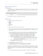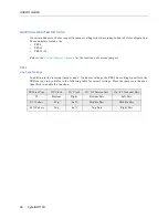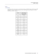
USER’S GUIDE
86 CyberSWITCH
A
DAPTER
I
NTERRUPT
AND
I/O A
DDRESS
S
ETTINGS
WAN A
DAPTERS
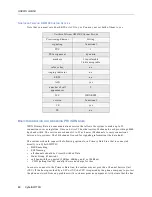
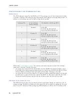
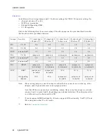
The WAN adapters (except for the RS-232 and V.35) use jumpers to set the interrupt and switches
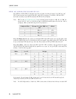
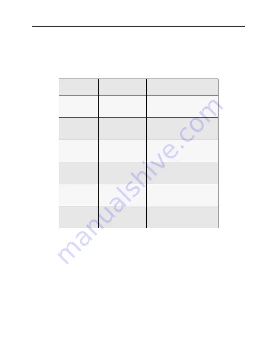
to set the I/O address. The following chart contains the WAN adapter’s interrupt jumper and I/O
address switch settings required for each configured slot number.
Refer to the
System Adapters Appendix
for location and numbering conventions of the interrupt
block and I/O switch. Note the following:
•
concerning the interrupt block: On some boards, such as the PRI-8, the interrupt block is num-
bered from left to right, beginning with position 3 on the left. On the PRI-23 and PRI-23/30, the
interrupt block is numbered from right to left, with position 3 starting on the right.
•
concerning the I/O Switch: If the adapter’s I/O address switches are labeled with open as opposed
to either off or on, open corresponds to off. On the PRI-23/30, S8 on the I/O Switch is not used.
The board should function properly with the switch in either the ON or OFF position.
DM-8 A
DAPTER
I/O A
DDRESS
S
ETTINGS
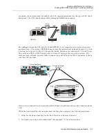
The DM-8 is unique in that it has no interrupts, and uses jumpers instead of switches for its I/O
address settings. The DM-8 will take on the interrupt of the slot in which it is configured. You only
need to set its I/O address. When configuring DM-8 adapters, use 380 for the I/O address of the
Configured Slot
Interrupt Jumper
(Interrupt Block)
I/O Address Switch Setting (SW1)
1
Position 3
Value 340
S1, S2, S3, S4, S5, S6, S7, S8
on, on, on, off, on, off, off, off
2
Position 11
Value 348
S1, S2, S3, S4, S5, S6, S7, S8
off, on, on, off, on, off, off, off
3
Position 5
Value 350
S1, S2, S3, S4, S5, S6, S7, S8
on, off, on, off, on, off, off, off
4
Position 10
Value 358
S1, S2, S3, S4, S5, S6, S7, S8
off, off, on, off, on, off, off, off
5
Position 7
Value 360
S1, S2, S3, S4, S5, S6, S7, S8
on, on, off, off, on, off, off, off
6
Position 12
Value 368
S1, S2, S3, S4, S5, S6, S7, S8
off, on, off, off, on, off, off, off

