Chapter 7: AT Commands and Registers
7-50
CSMIM-T1 Hardware Installation Guide
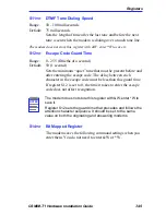
S25=
n
Delay to DTR and Asynchronous Time Delay
Range:
Delay to DTR: 0 - 255 hundredths of a second
Async mode: 0 - 255 seconds
Default:
Delay to DTR: 5 hundredths of a second (0.05 seconds)
Async mode: 5 seconds and 0.05 seconds
Delay to DTR: During asynchronous mode with &M2 or &M3
set, the modem ignores an On-to-Off transition of DTR that is
less than the register S25 time delay.
Asynchronous time delay: Register S25 sets the number of
seconds the modem waits to check DTR after establishing a
connection. After this time delay, the Delay to DTR time delay
described above takes effect when loss of DTR occurs.
S27=
n
Bit Mapped Register (Table 7-13)
Table 7-13
Saved Command Settings with S27
:
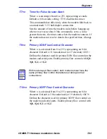
T0=
n
Timer for V.22bis, V.22, and V.32 Modes During
Multi-Protocol Answer
Where n is an integer from 0 to 255, in tenths of a second.
Default is 40 (4 seconds).
NOTE
If you use register S23 to change the parity set automatically or
set by -On, the same number of data and stop bits used before
the change is retained. For example, if 8 data bits and even
parity is set (-O6) and you change register S23 to odd parity,
the 8 data bits and 1 parity bit are retained. However, the parity
becomes odd instead of even, changing the Serial-Port Parity
command setting to -O5.
Bit
Position
Function
Decimal Value
6
answer tone when at 1200
bps
0
1
ITU-T V.22bis/V.22
Bell 212A when supported
7
not used
Summary of Contents for CSMIM-T1
Page 2: ......
Page 8: ...viii CSMIM T1 Hardware Installation Guide ...
Page 26: ...Chapter 1 INTRODUCTION 1 14 CSMIM T1 Hardware Installation Guide ...
Page 84: ...Chapter 4 CSMIM T1 Parameters 4 16 CSMIM T1 Hardware Installation Guide ...
Page 184: ...Chapter 7 AT Commands and Registers 7 58 CSMIM T1 Hardware Installation Guide ...
Page 188: ...Appendix A PORT PIN SIGNAL ALLOCATIONS A 4 CSMIM T1 Hardware Installation Guide ...


