Chapter 7: AT Commands and Registers
7-56
CSMIM-T1 Hardware Installation Guide
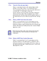
:T19=
n
Bit Mapped Register
Where n is an integer from 0 to 255 (see below for the valid
values for n). Default is 1.
This command controls MNP link control as follows:
Table 7-15
MNP Link Control
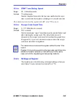
:T22=n
DSR Timer
Where n is an integer from 0 to 255 (in increments of 12.5
milliseconds). Default is 34 (425 milliseconds).
After DCD and/or CTS drop, :T22 identifies how long the
modem waits before DSR is dropped when disconnecting. For
example, if \D2 and &C1 are set, when DCD and CTS drop, the
modem then waits the amount of time specified by :T22 before
dropping DSR.
:T23=
n
Bit Mapped Register (Table 7-16)
Table 7-16
:T23 Settings
Bit
Position
Function
0
0
Modem keeps a non-MNP10 1200 bps connection if no
MNP link activity is received from the remote modem.
1
Modem disconnects a non-MNP10 1200 bps connection if
no MNP link activity is received from the remote modem
for two minutes.
Bit
Position
Function
Decimal Value
0,1
not used
4
Rate negotiation at
start-up
1. At the start of a V.32 connection,
makes modem examine line quality
and set speed accordingly.
2. Disabled.
6,7
not used
Summary of Contents for CSMIM-T1
Page 2: ......
Page 8: ...viii CSMIM T1 Hardware Installation Guide ...
Page 26: ...Chapter 1 INTRODUCTION 1 14 CSMIM T1 Hardware Installation Guide ...
Page 84: ...Chapter 4 CSMIM T1 Parameters 4 16 CSMIM T1 Hardware Installation Guide ...
Page 184: ...Chapter 7 AT Commands and Registers 7 58 CSMIM T1 Hardware Installation Guide ...
Page 188: ...Appendix A PORT PIN SIGNAL ALLOCATIONS A 4 CSMIM T1 Hardware Installation Guide ...


