CyberSWITCH 17
C
ABLING
The ISDN Connection
C
YBER
SWITCH
S
R
EQUIRING
DSU
S
For countries that require DSUs (for example, Japan), your CyberSWITCH will not have an internal
NT-1. You will need to use an external MJ and DSU in your connection to the network.
C
ONNECTION
I
NSTRUCTIONS
1.
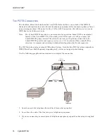
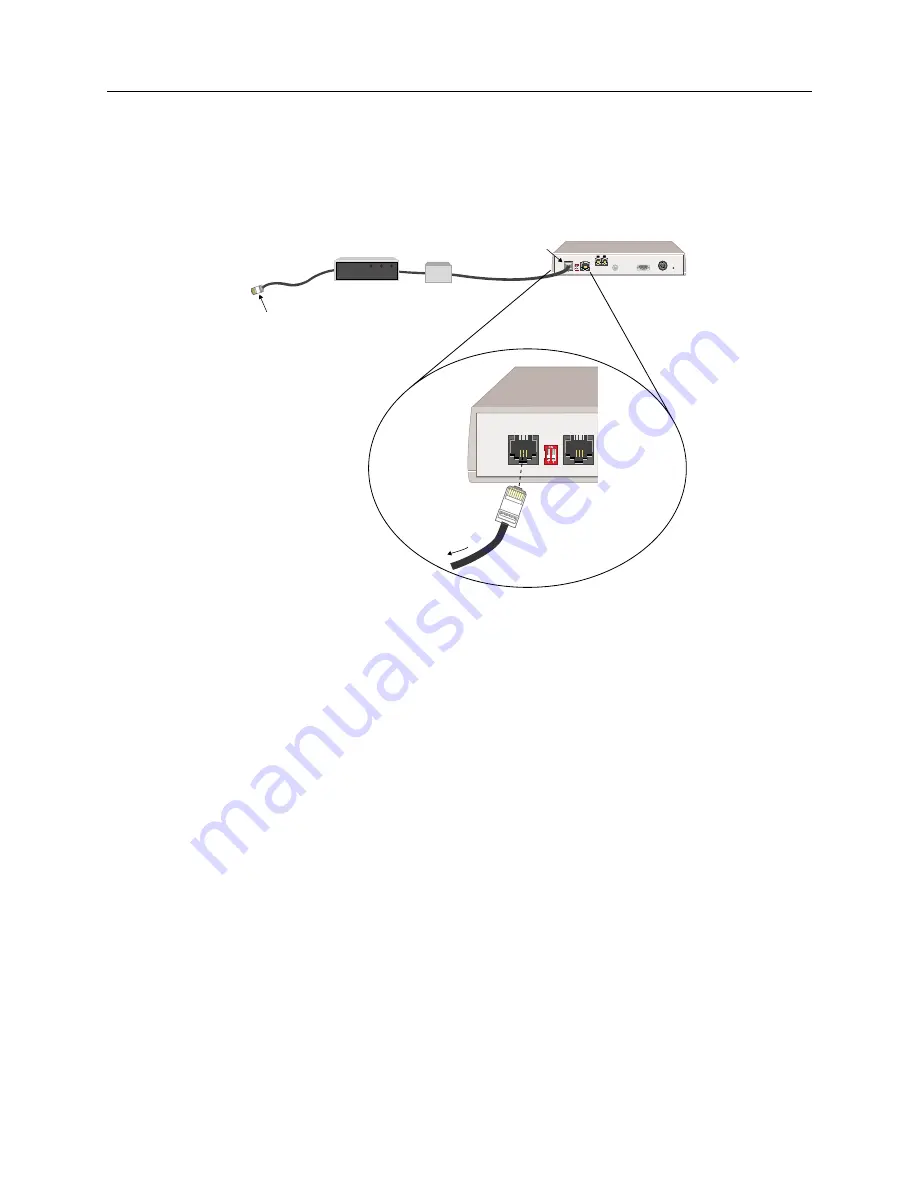
If you are not using an CyberSWITCH with an internal NT-1:
a.
Connect the CyberSWITCH to required intermediary devices (NT-1, or a MJ and CSU)
using a straight through cable (RJ45 connectors and twisted pair).
b.
Connect the intermediary device to the network (for example, to your ISDN phone jack).
2.
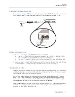
If you are using an CyberSWITCH with an internal NT-1, simply connect the CyberSWITCH to
the network using a straight through cable (RJ45 connectors with twisted pair).
T
ERMINATION
S
WITCHES
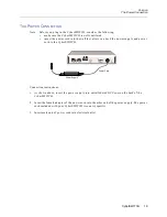
On the CyberSWITCH’s back panel (to the right of the BRI connector) there are a pair of termination
switches for multipoint connections. These switches are labeled Term. These DIP switches control
the terminating resistors for the Basic Rate Interface.
You must set both switches in the same direction or improper operation may result. The small
arrow points in the direction of the on position. When the switches are on, the resistors for the
connector are providing termination for the BRI line. Conversely, when the switches are off, the
resistors for the connector are not providing termination for the BRI line.
On an S/T interface, it is important to have the switches set correctly. On a U interface, the circuitry
is intended to operate properly no matter which switch setting is used; however, optimum
operation is achieved with the switches off.
BRI Term 10BT
BRI Term 10BT 10B2 Console DCPower Reset
1 2
RJ-45 Connector
Twisted Pair
To ISDN
Source
RJ-45
Connector
RJ-45
Twisted Pair
To ISDN Source
DSU
MJ


