background image

Small Office Remote Access Switch      43

S

PECIAL

 F

EATURES

Configuring Hardware Filters

6.

From the displayed list, select the type of POTS priority you want for this device.
a.

You may select Preemption of 2nd B-Channel by POTS when both B-channels are active to this 
device. If you select this priority, one of the two active data calls to this device will be 
preempted to service an incoming/outgoing phone call.

b.

You may select Disconnection by POTS for Last B-Channel when a single B-channel is used 
for a data call for this device. If you select this priority, this last B-channel may be 
disconnected to service an incoming/outgoing phone call. By configuring this option, you 
are implicitly enabling preemption of this device.

c.

You may also select None of the above. If you select this priority, the CyberSWITCH will not 
preempt or disconnect any active data calls to service an incoming/outgoing phone call.

C

ONFIGURING

 H

ARDWARE

 F

ILTERS

This feature allows the CyberSWITCH to increase its bridging performance when heavy local 
unicast traffic is present. Hardware filters let you move the burden of filtering the unicast local 
traffic from the CPU to the ethernet controller. This results in both an increase in performance and 
a reduction in dropped packets. As a default, this feature is disabled.

Note:

If bridging is disabled, hardware filters have no affect. 

In order to use hardware filters, the CyberSWITCH must have a list of destination MAC addresses. 
The CyberSWITCH obtains the addresses in two ways: manually and automatically. 

In the manual mode, you enter the list of destination MAC addresses. When the CyberSWITCH 
software initializes in this mode, no bridge learning occurs. Instead, the bridge will skip the 
learning phase and move directly to the forwarding phase. The CyberSWITCH will check to see if 
the incoming packet’s destination bridge address is on the configured list of addressees. Thus, 
when a packet destined for one of the addresses in the list is received, it will be bridged normally. 
Multicast frames are handled the same regardless of whether this feature is enabled or not. Unicast 
frames destined for MAC addresses not configured manually will not be bridged. Up to 63 
destination MAC addresses can be configured in this mode.

In the auto mode, you specify a time limit for learning MAC addresses and the maximum number 
of addresses the CyberSWITCH can learn. When the CyberSWITCH software initializes in this 
mode, the bridge will use its normal phases. Once it reaches the forwarding phase, bridging will 
progress as if hardware filtering were not enabled. As the bridge learns about remote MAC 
addresses, they are added to the MAC address list for hardware filtering. Once either the time limit 
or the limit of number of addresses is reached, the hardware filtering feature will be enabled. A 
message is then written to the log.

To configure the hardware filters feature:

1.

Select Options from the main CFGEDIT menu.

2.

Select Bridging from the options menu.

3.

If bridging is not enabled, follow the onscreen instructions to enable bridging.

4.

Select Enable/Disable the MAC H/W Filtering Feature from the bridging menu.

5.

Follow onscreen instructions to enable hardware filtering.

Summary of Contents for CyberSWITCH CSX150

Page 1: ...SMALL OFFICE REMOTE ACCESS SWITCH QUICK START Release 7 2 Cabletron Systems 603 332 9400 phone 603 337 3075 fax support ctron com 150 R E M O T E A C C E S S S W I T C H Small Office Small Office...

Page 2: ...TED TO THIS MANUAL OR THE INFORMATION CONTAINED IN IT EVEN IF CABLETRON SYSTEMS HAS BEEN ADVISED OF KNOWN OR SHOULD HAVE KNOWN THE POSSIBILITY OF SUCH DAMAGES Copyright 1998 by Cabletron Systems Inc A...

Page 3: ...cluding one or more U S Patents No 4701745 5016009 5126739 and 5146221 and other pending patents Telenetworks Copyright 1991 92 93 by Telenetworks All rights reserved FCC NOTICE This device complies w...

Page 4: ...ontrol Council for Interference by Information Technology Equipment VCCI If this equipment is used in a domestic environment radio disturbance may arise When such trouble occurs the user may be requir...

Page 5: ...ection 18 The Power Connection 19 Basics 20 Reading the LED Indicators 20 Accessing the Release Notes 20 Safety Considerations 21 Accessing the CyberSWITCH 21 Connecting an Administration Console 21 C...

Page 6: ...uration for Site Central 36 Configuration for Site Remote 37 AppleTalk Router to AppleTalk Router Configuration 38 Configuration for Site Central 38 Configuration for Site Remote 39 Special Features 4...

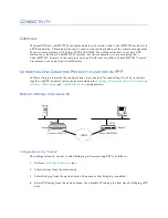
Page 7: ...ith instructions for connecting the CyberSWITCH to your PC several methods for ISDN connections and completing a POTS connection Basics This chapter gives detailed instructions on the initial installa...

Page 8: ...of the cabling processes Note If a cable you need is not among the cables included with your CyberSWITCH shipment order the cable separately through Cabletron or your distributor THE PC TO CYBERSWITC...

Page 9: ...nnection you will use Use the following graphic and instructions to complete the connection 1 Connect your PC to the Hub using the supplied straight through cable RJ 45 connectors with twisted pair 2...

Page 10: ...ion 1 Connect your PC to the CyberSWITCH using a crossover cable This cable is a custom made cable using RJ 45 connectors and twisted pair Order this cable through Cabletron or your Distributor The cr...

Page 11: ...f you wish to make your own the pinouts for the crossover cable s connectors are color coded as follows 12345678 12345678 1 2 4 5 3 6 7 8 1 2 4 5 3 6 7 8 wht ora ora wht wht blu blu wht wht grn grn wh...

Page 12: ...nector to the 10Base2 port of your PC and one to the10Base2 port of the CyberSWITCH 2 Connect one end of a 10Base2 cable BNC connectors with thin wire coax to your PC s BNC T connector and the other e...

Page 13: ...yberSWITCH for the modem you will use connect a modem to the CyberSWITCH using the Console connection connect the modem to the analog line use a standard PC modem RS232 cable for this do not use the s...

Page 14: ...he supplied cable To complete the cabling refer to the following graphic and instructions 1 Connect one end of a Null Modem to your PC serial port 2 Connect the other end of the Null Modem to the Cybe...

Page 15: ...le The method you use depends on the country you live in and whether or not you have an CyberSWITCH with the internal NT 1 option CYBERSWITCHS WITH INTERNAL NT 1S For countries that require the custom...

Page 16: ...ernal NT 1 you will need to use an external NT 1 in your connection to the network Issuing the ver command will tell you whether or not your CyberSWITCH has an internal NT 1 BRI Term 10BT BRI Term 10B...

Page 17: ...panel to the right of the BRI connector there are a pair of termination switches for multipoint connections These switches are labeled Term These DIP switches control the terminating resistors for th...

Page 18: ...rely on the phones connected to the CyberSWITCH ports for emergency service i e 911 In a home office or small office situation we recommend retaining a standard analog phone line for emergencies The P...

Page 19: ...supply and power cord to the CyberSWITCH Connection instructions 1 As shown above insert the power supply into outlet labeled DC Power on the back of the CyberSWITCH 2 Insert the female adapter of the...

Page 20: ...lit 2 The service indicator will light up for the duration of the initialization tests It will then blink if there is a problem For example it will blink if your LAN is not properly terminated For fur...

Page 21: ...mulation program The second method is to Telnet to the system The third method uses an AMP connection We describe each of these methods below CONNECTING AN ADMINISTRATION CONSOLE There are two ways to...

Page 22: ...art command 7 Change the communications package you are using to the same baud rate To change the baud rate using Manage Mode 1 Enter the Manage Mode by entering the following command manage 2 At the...

Page 23: ...e your CyberSWITCH Refer to Cabling for AMP cabling instructions LOGIN ON THE CYBERSWITCH Once you have a connection to the CyberSWITCH you will be presented with a prompt to enter your log in id Use...

Page 24: ...change the configuration without interrupting the current execution state of the system software But because it is dynamic Manage Mode does have its limitations So when making configuration changes y...

Page 25: ...PAN ipipxat fr directory LOCAL SOFTWARE UPGRADE To perform a local upgrade use any valid local administration console as defined in Connecting an Administration Console Update the SSB first if the Rel...

Page 26: ...ally reboot LOCAL UPGRADE OF THE OPERATIONAL SOFTWARE OSW To locally upgrade the operational software OSW of your system follow these steps 1 Change the CyberSWITCH system s baud rate to be the fastes...

Page 27: ...file due to insufficient Flash File System space Please delete unnecessary files from the system It is possible that you will not have enough room in the SYSTEM directory to TFTP the upgrade file to t...

Page 28: ...ftware follow these steps 1 From the PC workstation Telnet to the CyberSWITCH and login as admin 2 Verify that the system is ready to receive TFTP upgrades Enter MANAGE MODE by typing manage RET at th...

Page 29: ...e upgraded correctly If the upgrade did not occur check the system log with the dr command to find any potential problems and retry CHANGE DEFAULTS TO SECURE SYSTEM The system is preconfigured with de...

Page 30: ...ring Be careful passwords are uppercase and lowercase sensitive RETURN CONFIGURATION TO FACTORY DEFAULTS The default configuration files are located on the CSX150 Documentation and Set Up Utility CD I...

Page 31: ...enter NULLMODEM if you are using the AMP port for a regular modem enter a name you define for the modem enter the baud rate enter the data bits enter the stop bits enter the parity value select the f...

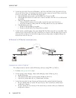
Page 32: ...two of our products together via PPP Separate instructions are included for bridging IP routing with an UnNumbered Interface IPX routing and AppleTalk routing configurations BRIDGE TO BRIDGE CONFIGUR...

Page 33: ...have to specify the method that you will use determine how to make bridge dial out calls The two methods and how to configure them are listed below a Select Options from the main menu then the bridgin...

Page 34: ...t the bridge dial out configuration is slightly different for Remote than it was for Central IP ROUTER TO IP ROUTER CONFIGURATION CONFIGURATION FOR SITE CENTRAL The configuration on Central to allow I...

Page 35: ...configuration on Remote to allow IP Routing to Central using PPP is as follows 1 Perform initial configuration steps 2 Under Options select Bridging then disable bridging Select IP Routing then a Enab...

Page 36: ...Under Security select System Options and Information then under System Information a Set your System Name Central This matches up with Central device information configured on Remote b Set your System...

Page 37: ...select System Options and Information then under System Information a Set your System Name Remote This matches up with Remote device information configured on Central b Set your System Secret Remote_S...

Page 38: ...d Under AppleTalk Information you must Enter 0 0 for the AppleTalk address Enable AppleTalk Routing Enable making calls for AppleTalk data 3 Under Options select AppleTalk Routing then a Enable AppleT...

Page 39: ...rform initial configuration steps 2 Under Security select Device Level Databases select On node Device Entries then add a device where the Device Name Central must match the system name on Central Whe...

Page 40: ...ter 0 0 as the next hop it s over an unnumbered link Enter Central as the next hop s device name Enter 2 as the number of hops for this route Enter Engineering as Central s default zone name Enter Mar...

Page 41: ...matically uses it when its allocated data link is busy For example in a one person sales office you could use the forward incoming feature to always ring on the first line which would attach to the te...

Page 42: ...e Outbound if Primary is Busy If you enable this option an outbound call from the specified jack can use any available datalink that supports voice or voice data if the primary phone number is busy Th...

Page 43: ...o ways manually and automatically In the manual mode you enter the list of destination MAC addresses When the CyberSWITCH software initializes in this mode no bridge learning occurs Instead the bridge...

Page 44: ...value for the maximum After the maximum number of addresses to learn has been met the CyberSWITCH stops learning addresses and enters the forwarding state d Select Address Learning Time Out enter the...

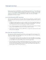
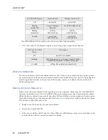
Page 45: ...ot shine 2 The TX indicator signifies that the CyberSWITCH has transmitted data to the LAN TX flashes whenever the CyberSWITCH sends at least 128 bytes of data on the LAN 3 The RX indicator signifies...

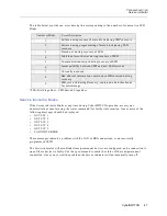
Page 46: ...ndicator remains lit the other LEDs will blink a certain number of times pause then blink that number of times again See following table This pattern will be repeated five times The actions to take if...

Page 47: ...med SPID The Service indicator will also blink if semipermanent devices are configured and a connection to one of these devices is faulty Use the sp command to check the status of the semipermanent co...

Page 48: ...notices 3 configuration tools 23 D data links 31 D CHAN indicator 20 45 defaults returning to factory defaults 30 system defaults 29 DOC notice 4 DSU 17 E encoding standard POTS 41 exit 24 F factory...

Page 49: ...feature 24 remote devices 45 via PPP 32 restart 22 RX indicator 20 45 S S T interface and the termination switches 17 safety considerations 21 security securing the system 29 service indicator 20 46...

Reviews: