Page 2-8
INSTALLATION
•
Carefully remove the adapter from its protective pouch, and
visually inspect it.
•
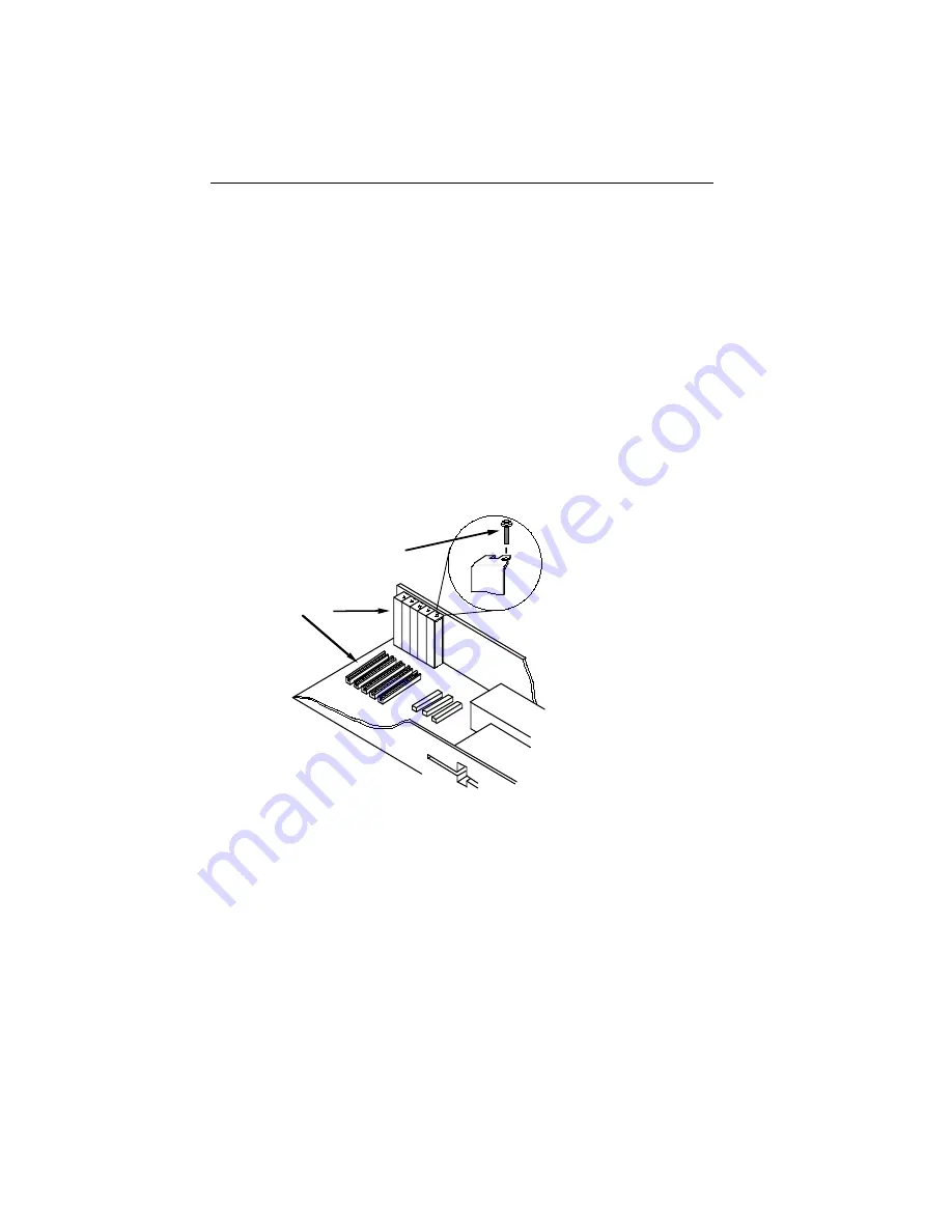
Remove the backplate (2, Fig. 2-6) from the selected slot (3)
by removing the screw (1) holding the backplate in place, and
sliding the backplate out of the slot as shown in Figure 2-6.
Carefully insert the adapter into the expansion slot as shown in
Figures 2-7 and 2-8. Orient the adapter (1) so the PC edge bus
connector (2) is pointed down and the ports face out the back of
the PC. Align the adapter so the PC bus edge connector is lined up
with the expansion slot (3), and firmly press, but do not force, the
adapter into the slot.
3
2
1
1. Screw
2. Backplate
3. Expansion Slot
Figure 2-6. Backplate Detail


