Technical Specifications
A-5
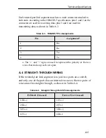
Each twisted-pair link segment must have a male connector attached to
both ends. According to the 10BASE-T specification, pins 1 and 2 on the
connector are used for receiving data; pins 3 and 6 are used for
transmitting data, as shown in Table A-3.
a. The “+” and “-” signs are used to represent the polarity of the two
wires that make up each wire pair.
A.4 STRAIGHT-THROUGH WIRING
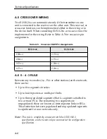
If the twisted-pair link segment is to join two ports on a switch,
and only one of the ports has an internal crossover, the two pairs of
wires must be straight-through, as shown in Table A-4.
Table A-3. 10BASE-T Pin Assignments
Pin
Assignment
a
1
Rx+
2
Rx-
3
Tx+
6
Tx-
Table A-4. Straight-Through RJ45 Pin Assignments
ELS10-26 (Crossed)
Device (Not Crossed)
1 (Rx+)
1 (Tx+)
2 (Rx-)
2 (Tx-)
3 (Tx+)
3 (Rx+)
6 (Tx-)
6 (Rx-)
Summary of Contents for ELS10-26TX
Page 2: ......
Page 10: ...viii Contents...
Page 48: ...2 16 Unpacking and Installing Your ELS10 26...
Page 92: ...5 8 ELS10 26 Diagnostics and Troubleshooting...
Page 112: ...B 12 Glossary...
Page 116: ...Index I 4 W wiring crossover A 6 straight through A 5...

