background image


EMC32-12

Installation Guide


Cabletron Systems, P.O. Box 5005, Rochester, NH 03866-5005

P/N 9031631-02

Summary of Contents for EMC32-12

Page 1: ...EMC32 12 Installation Guide Cabletron Systems P O Box 5005 Rochester NH 03866 5005 P N 9031631 02 ...

Page 2: ...ING BUT NOT LIMITED TO LOST PROFITS ARISING OUT OF OR RELATED TO THIS MANUAL OR THE INFORMATION CONTAINED IN IT EVEN IF CABLETRON SYS TEMS HAS BEEN ADVISED OF KNOWN OR SHOULD HAVE KNOWN THE POSSI BILITY OF SUCH DAMAGES Copyright November 1995 by Cabletron Systems Inc P O Box 5005 Rochester NH 03866 5005 All Rights Reserved Printed in the United States of America Part Number 9031631 02 CompuServe i...

Page 3: ...F LIABILITY FOR CONSEQUENTIAL OR INCIDENTAL DAMAG ES OR ON THE DURATION OR LIMITATION OF IMPLIED WARRANTIES IN SOME INSTANCES THE ABOVE LIMITATIONS AND EXCLUSIONS MAY NOT AP PLY TO YOU UNITED STATES GOVERNMENT RESTRICTED RIGHTS The enclosed product a was developed solely at private expense b contains restrict ed computer software submitted with restricted rights in accordance with Section 52227 19...

Page 4: ...onnect it to a module The EMC32 12 is a twelve port RJ 45 adapter that allows up to twelve Ethernet connections to a single 50 pin champ connector and can be used on any single Telco module Because of the proximity of the Champ connectors on a multiple telco module more than one EMC32 12 cannot be used The exception to this is the 9E133 36 which is designed to accept three EMC32 12 s There are no ...

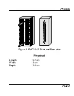
Page 5: ...spect the unit for any damage If any damage is found contact Cabletron Systems immediately 3 Remove the plastic cover from the Champ connection 4 Position RJ 45 port 1 toward the bottom of the module See figure 1 and insert the EMC32 12 firmly into the connector 5 Tighten thumbscrews to ensure proper connection ...

Page 6: ...Physical Page 3 Figure 1 EMC32 12 Front and Rear view Physical Length 9 7 cm Width 3 cm Depth 3 8 cm 11 9 7 5 3 1 12 10 8 6 4 2 ...

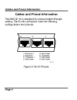
Page 7: ...The EMC32 12 is designed to accept straight through cabling The RJ 45 connectors have the following configurations and pinouts Figure 2 RJ 45 Pinouts 1 2 3 4 5 6 7 8 1 Receive 5 Not Used 2 Receive 6 Transmit 3 Transmit 7 Not Used 4 Not Used 8 Not Used 12 10 8 09162_02 ...

Page 8: ...3 335 4743 CompuServe GO CTRON from any prompt Internet Mail support ctron com Anonymous ftp 134 141 197 25 If you have any questions comments or suggestions concerning this manual you can also contact Cabletron Technical Support at the following address or telephone number Cabletron Systems Inc P O Box 5005 Rochester NH 03866 5005 603 332 9400 ...

Reviews: