background image

Connecting to the Network

DELHE-UA User’s Guide

2-11

Figure 2-5

DELTX-UI Crossover Switch

A schematic of a straight-through and a crossover cable is shown in 
Figure 2-6. If the wires do not cross over, use the switch on the 
DELTX-UI to internally cross over the RJ45 port. Figure 2-5 shows how 
to properly set the DELTX-UI crossover switch.

DELTX-UI

10

100

=

x

fecrossover

Position =
(not crossed over)

1. TX+
2. TX-
3. RX+
4. NC

5. NC
6. RX-
7. NC
8. NC

Position X
(crossed over)

1. RX+
2. RX-
3. TX+
4. NC

5. NC
6. TX-
7. NC
8. NC

Summary of Contents for Expansion module DELHE-UA

Page 1: ...DIGITAL Fast Ethernet Interface Module DELHE UA User s Guide ...

Page 2: ......

Page 3: ...net Interface Module DELHE UA User s Guide Part Number 9032765 September 1998 This book describes the DELHE UA features and how to install and troubleshoot the equipment Revision Update Information This is a new document ...

Page 4: ...ron Systems Inc DIGITAL and the DIGITAL logo are trademarks of Digital Equipment Corporation All other product names mentioned in this manual may be trademarks or registered trademarks of their respective companies UNITED STATES GOVERNMENT RESTRICTED RIGHTS The enclosed product a was developed solely at private expense b contains restricted computer software submitted with restricted rights in acc...

Page 5: ...Interference Regulations of the Canadian Department of Communications Le présent appareil numérique n émet pas de bruits radioélectriques dépassant les limites applicables aux appareils numériques de la class A prescrites dans le Règlement sur le brouillage radioélectrique édicté par le ministère des Communications du Canada VCCI Notice Class A Computing Device Taiwanese Notice Class A Computing D...

Page 6: ...nterpreted and governed under the laws and in the state and federal courts of New Hampshire You accept the personal jurisdiction and venue of the New Hampshire courts EXCLUSION OF WARRANTY AND DISCLAIMER OF LIABILITY 1 EXCLUSION OF WARRANTY Except as may be specifically provided by Cabletron in writing Cabletron makes no warranty expressed or implied concerning the Program including its documentat...

Page 7: ...dization When operating within their performance limitations laser transceiver output meets the Class 1 accessible emission limit of all three standards Class 1 levels of laser radiation are not considered hazardous SAFETY INFORMATION CLASS 1 LASER TRANSCEIVERS LASER RADIATION AND CONNECTORS When the connector is in place all laser radiation remains within the fiber The maximum amount of radiant p...

Page 8: ...N 60950 Equipment Type Environment Networking Equipment for use in a Commercial or Light Industrial Environment We the undersigned hereby declare under our sole responsibility that the equipment packaged with this notice conforms to the above directives Manufacturer Legal Representative in Europe Mr Ronald Fotino Mr J Solari ___________________________________ ___________________________________ F...

Page 9: ...Duplex Switched Ethernet 1 2 1 1 4 LANVIEW Diagnostic LEDs 1 2 1 2 FEPIM Options 1 2 CHAPTER 2 INSTALLATION 2 1 Unpacking the DELHE UA 2 1 2 2 Installing Fast Ethernet Port Interface Modules 2 2 2 3 Installing the DELHE UA 2 5 2 3 1 Installing the DELHE UA in an Interface Module 2 5 2 4 Connecting to the Network 2 8 2 4 1 Connecting a Fiber Optic Segment to the FEPIM 2 9 2 4 2 Connecting a Twisted...

Page 10: ...LHE UA User s Guide A 1 Physical Properties A 1 A 2 Environmental Requirements A 1 A 3 FEPIM Options A 1 A 4 Regulatory Compliance A 2 APPENDIX B FEPIM SPECIFICATIONS B 1 DELTX UI B 1 B 2 DELFX UI B 2 B 3 DELF3 UI B 3 ...

Page 11: ...PIM Coverplate 2 3 2 2 Installing the FEPIM 2 4 2 3 Removing the HSIM Coverplate 2 6 2 4 Installing the DELHE UA 2 7 2 5 DELTX UI Crossover Switch 2 11 2 6 Twisted Pair Cabling 2 12 3 1 DELHE UA LANVIEW LEDs 3 1 3 2 DELTX UI LED 3 2 B 1 DELTX UI Pinouts B 1 B 2 DELFX UI B 2 B 3 DELF3 UI B 3 ...

Page 12: ...Tables x DELHE UA User s Guide TABLES Table Page 1 1 FEPIM Options 1 2 3 1 DELHE UA LEDs 3 2 3 2 10 100 LED Indications When RX LED Is On 3 3 3 3 10 100 LED Indications When RX LED Is Off 3 3 ...

Page 13: ...wledge of Ethernet and data communications networks and their physical layer components is helpful when installing this device STRUCTURE OF THIS GUIDE This guide is organized as follows Chapter 1 Introduction describes the DELHE UA features Chapter 2 Installation describes how to install a DELHE UA into an interface module host platform Chapter 3 LANVIEW LEDs describes how to use the DELHE UA LEDs...

Page 14: ...ocedures in these documents where appropriate but does not repeat them These documents can be obtained on the World Wide Web in Adobe Acrobat Portable Document Format PDF at the sites listed in the World Wide Web section of this Preface Note symbol Calls the reader s attention to any item of information that may be of special importance Caution symbol Contains information essential to avoid damage...

Page 15: ...ling have the following information ready A description of the failure A description of any action s already taken to resolve the problem e g changing mode switches rebooting the unit etc A description of your network environment layout cable type etc Network load and frame size at the time of trouble if known The device history i e have you returned the device before is this a recurring problem e...

Page 16: ......

Page 17: ...nten DANGER Déconseille à l utilisateur d exécuter une action pouvant entraîner des dommages matériels corporels voire même la mort AVISO Previene contra una acción que podría dañar el equipo provocar daños personales o la muerte CAUTION Contains information essential to avoid damage to the equipment ACHTUNG Liefert wichtige Informationen um einen Geräteschaden zu vermeiden ATTENTION Informations ...

Page 18: ...lte ordnungsgemäß ange bracht sein bevor das Netzkabel wieder ange schlossen wird DANGER Avant de rebrancher le cordon d alimentation vérifiez que le couvercle du châssis est bien en place AVISO Asegúrese de que la cubierta del chasis esté en su sitio antes de volver a conectar el cable de alimentación WARNING Certain FEPIMs use Class 1 lasers Do not use optical instruments to view the laser outpu...

Page 19: ...rd When viewing the output optical port power must be removed from the network adapter VORSICHT DELF3 UI verwendet Laser der Klasse 1 Verwenden Sie keine optischen Geräte um den Laserausgang zu betrachten da dies die Gefahr für die Augen erhöhen würde Wenn Sie den optischen Laserausgang betrachten wollen muß zuvor die Stromversorgung des Netzwerkadapters ausgeschaltet werden DANGER L appareil DELF...

Page 20: ...ectez toutes les précautions relatives à l électricité statique Si vous ne tenez pas compte de ces conseils vous risquez d endommager cet équipement PRECAUCIÓN DELVM UA FPIMs y el hub o módulo de host es sensible a la descarga estática Utilice una banda antiestática para la muñeca y observe todas las precauciones sobre estática durante este procedimiento Si no se cumple con estos requisitos se pue...

Page 21: ...DELHE UA selon le cas sont bien enfichés Dans le cas contraire les appareils DELHE UA et FEPIM risquent d être endommagés PRECAUCIÓN Asegúrese de que el conector FEPIM o DELHE UA está alineado con el DELHE UA módulo o patillas del conector del dispositivo para evitar la curvatura de las patillas Si no se hace así se pueden producir daños en el DELHE UA FEPIM módulo o dispositivo CAUTION Do not tou...

Page 22: ...en contact avec de la poussière de la saleté ou autres agents contaminants pouvant provoquer des erreurs de transmission de données Si les extrémités sont sales nettoyez les à l aide d un chiffon Un tampon de nettoyage de port optique imbibé d alcool isopropylique peut également être utilisé PRECAUCIÓN No toque los extremos de los filamentos de la fibra óptica ni permita que dichos extremos entren...

Page 23: ...ink capability through Fast Ethernet technology with different types of media 1 1 1 Connectivity The DELHE UA module supports Fast Ethernet technology using interchangeable Fast Ethernet Port Interface Modules FEPIMs The FEPIMs support three types of media connectivity RJ45 Category 5 unshielded twisted pair and SC connectors for either single or multimode fiber The FEPIMs support an uplink to 100...

Page 24: ...igured to operate in Full Duplex Switched Ethernet mode 1 1 4 LANVIEW Diagnostic LEDs Cabletron Systems provides a visual diagnostic and monitoring system called LANVIEW The DELHE UA LANVIEW LEDs help you quickly identify transmit and receive status Chapter 3 provides information on the DELHE UA LEDs and the DELTX UI LED 1 2 FEPIM OPTIONS The FEPIM options for the DELHE UA are listed in Table 1 1 ...

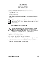
Page 25: ...dule in its antistatic bag until you are ready to install it 3 Attach the antistatic wrist strap refer to the instructions on the antistatic wrist strap package for proper use Before attempting to use the DELHE UA you should be familiar with the IEEE 802 3 802 3 10BASE T and 802 3u 100BASE T Specifications The DELHE UA and the host platform are sensitive to static discharges Use an antistatic stra...

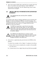
Page 26: ...ollows 1 Remove the coverplate from the port slot where the FEPIM will be installed To remove the coverplate refer to Figure 2 1 and proceed as follows a Remove the two screws fastening the coverplate to the standoffs Save the screws b Lift and remove the coverplate from the top of the front standoffs Only qualified personnel should perform installation procedures The DELF3 UI uses Class 1 lasers ...

Page 27: ... the connector 3 Align the FEPIM connector into the DELHE UA connector pins See Figure 2 2 Before installing a DELFX UI or DELF3 UI module into the host module remove the protective cover on the SC connector Ensure that the FEPIM connector aligns with the DELHE UA connector pins to prevent bending the pins This can damage both the DELHE UA and the FEPIM coverplate_remove FEPIM Coverplate Standoff ...

Page 28: ...ws enclosed in the FEPIM packaging The screw used to attach the rear of the FEPIM to the standoff is optional and not necessary for proper installation Refer to Figure 2 2 If SC protective covers were removed from a fiber FEPIM replace the covers until the port is connected to the network to reduce the chance of dust and contaminants entering the port DELFX UI 10 100 Front Standoffs Rear Standoff ...

Page 29: ...ched to them Write down the ports and label the cables to make it easier to reattach the network properly after the installation Then disconnect the cables from the ports 2 Attach the antistatic wrist strap refer to the instructions outlined on the antistatic wrist strap package 3 If the interface module is installed in a chassis unlock the top and bottom plastic locking tabs of the module facepla...

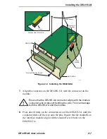
Page 30: ...he two faceplate mounting screws securing the HSIM coverplate and remove the coverplate See Figure 2 3 Figure 2 3 Removing the HSIM Coverplate 6 Refer to Figure 2 4 and place the DELHE UA behind the module faceplate Faceplate Mounting Screws DELHE UA Coverplate 2555_03 ...

Page 31: ...ay onto the pins Ensure that the standoffs on the interface module align with the standoff screw holes on the DELHE UA Ensure that the DELHE UA connector aligns with the module connector pins to prevent bending the pins This can damage both the DELHE UA and the module Faceplate Mounting Screws mounting Standoffs HSIM Connector DELHE UA Standoff Screws Connector top view Cutaway view of connector C...

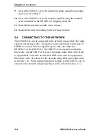
Page 32: ... can be connected to the network using either fiber optic cable or twisted pair cable The media chosen determines which type of FEPIM to be used When using fiber optic cable use either the DELFX UI or the DELF3 UI The DELFX UI is used for multimode fiber cable and the DELF3 UI is used for single mode fiber cable Refer to Appendix B for details on which FEPIM to use with the appropriate fiber optic...

Page 33: ...one device is connected to the receive port of the other device and vice versa If the fiber optic cable being used has SC style connectors that do not resemble MIC style connectors or has SC connectors on one end and a different type on the other such as ST connectors ensure that the proper crossover occurs Leave the protective covers in place when the connectors are not in use to prevent contamin...

Page 34: ... a link has not been established refer to Chapter 3 LANVIEW LEDs before contacting a DIGITAL representative 2 4 2 Connecting a Twisted Pair Segment to the DELTX UI A DELTX UI has an internal crossover switch When connecting a workstation use a straight through cable and set the FEPIM crossover switch shown in Figure 2 5 to the crossed over position marked with X When connecting networking devices ...

Page 35: ...s shown in Figure 2 6 If the wires do not cross over use the switch on the DELTX UI to internally cross over the RJ45 port Figure 2 5 shows how to properly set the DELTX UI crossover switch DELTX UI 10 100 x fecrossover Position not crossed over 1 TX 2 TX 3 RX 4 NC 5 NC 6 RX 7 NC 8 NC Position X crossed over 1 RX 2 RX 3 TX 4 NC 5 NC 6 TX 7 NC 8 NC ...

Page 36: ...rify that a link exists by checking that the port receive LED is on flashing amber blinking green or solid green If the receive LED is off perform the following steps until it is on a Verify that the 100BASE TX device at the other end of the twisted pair segment is powered up TX TX RX RX 2 1 3 6 TX TX 2 1 3 6 NOTE RX RX and TX TX must share a common color pair TO RJ45 Port 25041 08 RJ45 to RJ45 RX...

Page 37: ...roper pinouts c Check the cable for continuity d Make sure that the twisted pair connection meets cable specifications outlined in Appendix B e Confirm that the crossover switch is in the correct position If a link is not established refer to Chapter 3 LANVIEW LEDs for information before contacting a DIGITAL representative ...

Page 38: ......

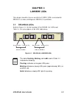
Page 39: ...EDs and Table 3 1 for a description of the LED indications Figure 3 1 DELHE UA LANVIEW LEDs The terms flashing blinking and solid used in Table 3 1 indicate the following Flashing indicates an irregular LED pulse Blinking indicates a steady LED pulse approximately 50 on and 50 off Solid indicates a steady LED light No pulsing DELHE UA FEPIM 1 FEPIM 2 SP Transmit TX Receive RX Transmit TX Receive R...

Page 40: ...escription of the 10 100 LED when the RX LED is on or off respectively Figure 3 2 DELTX UI LED Table 3 1 DELHE UA LEDs LED Color Definition Receive Green Link no activity Port enabled Green Blinking Link port disabled Amber Flashing Link activity Port enabled Off No link no activity Port enabled or disabled Red Solid Diagnostic failure Transmit Green Flashing Activity port enabled Amber Blinking P...

Page 41: ...dications When RX LED Is On LED Color Indication 10 100 Off DELTX UI is operating at 10 Mbps Green DELTX UI is operating at 100 Mbps No link exists if the associated port RX LED is off Table 3 3 10 100 LED Indications When RX LED Is Off LED Color Indication 10 100 Off No link or no cable attached DELTX UI forced to 10 Mbps operation or is manually set to auto negotiate mode Green No link or no cab...

Page 42: ......

Page 43: ...SICAL PROPERTIES A 2 ENVIRONMENTAL REQUIREMENTS A 3 FEPIM OPTIONS The FEPIM options for the DELHE UA include the DELTX UI DELFX UI and the DELF3 UI Refer to Appendix B for FEPIM specifications Dimensions 4 8H x 15 5W x 28 6D cm 1 9H x 6 1W x 11 3D in Weight 0 34 kg 0 75 lb MTBF Predicted 200 000 hours Operating Temperature 5 C to 40 C 41 F to 104 F Storage Temperature 30 C to 73 C 22 F to 164 F Op...

Page 44: ...OMPLIANCE This equipment meets the following safety and electromagnetic compatibility EMC requirements Safety UL 1950 CSA C22 2 No 950 EN 60950 IEC 950 and 73 23 EEC Electromagnetic Compatibility EMC FCC Part 15 EN 55022 CSA C108 8 EN 50082 1 VCCI V 3 89 336 EEC and AS NZS 3548 ...

Page 45: ...ector supporting Category 5 85 111 ohms Unshielded Twisted Pair UTP and Shielded Twisted Pair STP cabling The slide switch on the DELTX UI determines the crossover status of the cable pairs If the switch is on the X side the pairs are internally crossed over If the switch is on the side the pairs are not internally crossed over Figure B 1 shows the pinouts for the DELTX UI with the switch in each ...

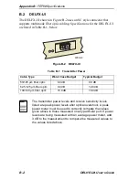
Page 46: ...cal Budget 50 125 µm fiber optic 6 0 dB 9 0 dB 62 5 125 µm fiber optic 9 0 dB 12 0 dB 100 140 µm fiber optic 15 0 dB 18 0 dB The transmitter power levels and receive sensitivity levels listed are peak power levels after optical overshoot A peak power meter must be used to correctly compare the values given above to those measured on any particular port If power levels are being measured with an av...

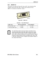
Page 47: ...get Typical Budget 8 125 µm fiber optic 10 0 dB 10 0 dB 12 5 125 µm fiber optic 10 0 dB 10 0 dB The transmitter power levels and receive sensitivity levels listed are peak power levels after optical overshoot A peak power meter must be used to correctly compare the values given above to those measured on any particular port If power levels are being measured with an average power meter add 3 dB to...

Page 48: ......

Page 49: ......

Page 50: ...9032765 Printed in U S A ...

Reviews: