background image


1-5

Introduction


Related Manuals


The manuals listed below should be used to supplement the procedures and 
technical data contained in this manual.

SmartSwitch 9000 Installation Guide

SmartSwitch 9000 9C300-1 Environmental Module User’s Guide

SmartSwitch 9000 9C214-1 AC Power Supply User’s Guide

INB Terminator Modules Installation Guide

SmartSwitch 9000 Module Local Management User’s Guide


Getting Help


For additional support related to this device or document, contact the Cabletron Systems Global Call 
Center:

Before calling the Cabletron Systems Global Call Center, have the following information ready:

Your Cabletron Systems service contract number 

A description of the failure

A description of any action(s) already taken to resolve the problem (e.g., changing mode switches, 
rebooting the unit, etc.)

The serial and revision numbers of all involved Cabletron Systems products in the network

A description of your network environment (layout, cable type, etc.)

Network load and frame size at the time of trouble (if known)

The device history (i.e., have you returned the device before, is this a recurring problem, etc.)

Any previous Return Material Authorization (RMA) numbers


Phone

(603) 332-9400

Internet mail

support@ctron.com

FTP

ctron.com (134.141.197.25)

Login 


anonymous


Password 


your email address


BBS

(603) 335-3358 

Modem setting

8N1: 8 data bits, No parity, 1 stop bit

For additional information about Cabletron Systems or its products, visit the 
World Wide Web site:


http://www.cabletron.com/ 


For technical support, select


Service and Support


.

To send comments or suggestions concerning this document, contact the 
Cabletron Systems Technical Writing Department via the following 
email address:


TechWriting@ctron.com


Make sure to include the document Part Number in the email message.

Summary of Contents for MMAC-Plus 9H421-12

Page 1: ...SmartSwitch 9000 9H421 12 9H422 12 and 9H429 12 User s Guide 9031928 03...

Page 2: ......

Page 3: ...AMAGES WHATSOEVER INCLUDING BUT NOT LIMITED TO LOST PROFITS ARISING OUT OF OR RELATED TO THIS MANUAL OR THE INFORMATION CONTAINED IN IT EVEN IF CABLETRON SYSTEMS HAS BEEN ADVISED OF KNOWN OR SHOULD HA...

Page 4: ...in which case the user will be required to correct the interference at his own expense WARNING Changes or modifications made to this device which are not expressly approved by the party responsible fo...

Page 5: ...Equipment for use in a Commercial or Light Industrial Environment We the undersigned hereby declare under our sole responsibility that the equipment packaged with this notice conforms to the above di...

Page 6: ...maintenance checks or adjustments The output is factory set and does not allow any user adjustment Class 1 Laser transceivers comply with the following safety standards 21 CFR 1040 10 and 1040 11 U S...

Page 7: ...or 55 x 10 6 watts Removing the optical connector from the transceiver allows laser radiation to emit directly from the optical port The maximum radiance from the optical port under worst case conditi...

Page 8: ...Notice vi...

Page 9: ...witch 9000 Chassis 2 6 The Reset Switch 2 8 Chapter 3 Operation FENIB 3 3 SmartSwitch ASIC 3 3 Traditional Switch 3 3 SecureFast Switch SFS 3 3 i960 Core 3 4 INB NIB 3 4 System Management Buses 3 4 SM...

Page 10: ...Contents viii Physical 5 2 Dimensions 5 2 Weight 5 2 Environment 5 2 Appendix A FEPIM Specifications FE 100TX A 1 FE 100FX A 2...

Page 11: ...e 100BASE FX single mode fiber SMF ports These modules connect to the SmartSwitch 9000 INB 2 backplane interface and employ the family of SmartSwitch ASICs a high performance switch design and an Inte...

Page 12: ...s in length when operating in half duplex point to point or full duplex Distance of links on a shared LAN in half duplex is 412 meters The 9H429 12 single mode SC connectors provide twelve Fast Ethern...

Page 13: ...bletron Enterprise MIBs LANVIEW LEDs The 9H421 12 9H422 12 and the 9H429 12 modules use LANVIEW the Cabletron Systems built in visual diagnostic and status monitoring system With LANVIEW LEDs you can...

Page 14: ...Introduction 1 4 Figure 1 1 The 9H421 12 9H429 12 and 9H422 12 Modules SMB CPU INB 9H421 12 FAST ENET SMB CPU INB 9H429 12 FAST ENET SMB INB 9H422 12 FAST ENET CPU...

Page 15: ...ooting the unit etc The serial and revision numbers of all involved Cabletron Systems products in the network A description of your network environment layout cable type etc Network load and frame siz...

Page 16: ...Introduction 1 6...

Page 17: ...examine the module checking for damage If any damage exists DO NOT install the module Contact Cabletron Systems Technical Support immediately Installing an FEPIM The 9H422 12 provides a slot for a Ca...

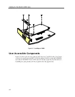
Page 18: ...ents Figure 2 2 shows the various components that are accessible to the user These consist of an eight position DIP switch explained below replaceable PROMs and sockets for RAM These will be used for...

Page 19: ...2 3 Installing the SmartSwitch 9000 Module Figure 2 2 9H422 12 User Accessible Components St SMB 10 FEPIM Connector Boot Prom Flash DRAM Dip Switches CNXSTATS Connector...

Page 20: ...12 and 9H429 12 User Accessible Components An eight position DIP switch is located on the module card as shown in Figure 2 2 and Figure 2 3 The function of the switches are listed in Table 2 1 SMB 10...

Page 21: ...in NVRAM when the module is powered down and remain there until the switch is toggled again 6 Force BootP Download Toggling this switch after pulling the board out of the SmartSwitch 9000 clears downl...

Page 22: ...ng receptacle in the lower right corner of the SmartSwitch 9000 chassis shown in Figure 2 4 3 The module is installed into the chassis by sliding it into slots and locking down both the top and bottom...

Page 23: ...the 9H421 12 9H422 12 and 9H429 12 Modules Metal Back Panel Module Guides Module Jack for ESD Wrist Strap Plastic Tab Warning Ensure that the circuit card is between the card guides Lock down the top...

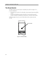
Page 24: ...s Pressing the reset switch twice within three seconds causes the processor i960 to reset Pressing and holding the switch on for three or more seconds causes the module to shutdown Momentarily pressin...

Page 25: ...tic speed selection The 9H421 12 and 9H429 12 are 100BASE FX compatible and operate only at 100 Mbps Each module can operate in either full duplex or half duplex mode Auto negotiation for 100BASE T mo...

Page 26: ...tch ASIC flags the error and does not forward the errored data packet to any outbound ports Once in this common format the SmartSwitch ASIC decides from header information the port destination of data...

Page 27: ...B backplane and LAN WAN interfaces on the front panel of SmartSwitch 9000 modules The SmartSwitch ASIC can operate in two modes as a traditional switch or as a SecureFast Switch SFS Traditional Switch...

Page 28: ...d from the INB the INB NIB reassembles the data blocks received from the INB back into canonical frames for transmission to the SmartSwitch ASIC then from the SmartSwitch ASIC to the front panel ports...

Page 29: ...supporting logic The diagnostic controller is designed to control the power up sequencing of modules monitor the 9H421 12 9H422 12 and the 9H429 12 input and output power parameters keep watch over t...

Page 30: ...h all control and management communication being serviced on the 8 bit out of band bus The INB can time slice its bandwidth using one of three methods The default method is standard TDM round robin ba...

Page 31: ...e module and may be used as an aid in troubleshooting Figure 4 1 and Figure 4 2 show the LANVIEW LEDs of the 9H421 12 9H422 12 and the 9H429 12 modules Figure 4 1 9H422 12 LANVIEW LEDs Port Transmit S...

Page 32: ...LANVIEW LEDs 4 2 Figure 4 2 9H421 12 and 9H429 12 LANVIEW LEDS SMB CPU INB FAST ENET Port Transmit System Status INB Transmit INB Receive Port Receive...

Page 33: ...testing Yellow Blinking Crippled Not fully operational i e one port may be bad Yellow Green Booting Module is performing its boot process Red Reset Module is resetting Red Blinking Failed Fatal error...

Page 34: ...NB fault Red Flashing FAULT or Error Flashing to steady on indicates rate Off No activity port enabled Table 4 4 Port Receive LEDs LED Color State Green Link no activity port enabled Green Flashing Li...

Page 35: ...64K buffer per port Standards IEEE 802 3u Network Interface 11 100BASE TX and 1 Cabletron FEPIM for the 9H422 12 12 Multi mode 100BASE FX for the 9H421 12 12 Single Mode 100BASE FX for the 9H429 12 S...

Page 36: ...MC requirements of EN 50082 1 IEC 801 2 ESD IEC 801 3 Radiated susceptibility IEC 801 4 EFT Service MTBF MHBK 217E 200 000 hrs MTTR 0 5 hr Physical Dimensions 35 0D x 44 0H x 3 0W centimeters 13 8D x...

Page 37: ...d Twisted Pair UTP cabling The slide switch on the FE 100TX determines the crossover status of the cable pairs If the switch is on the X side the pairs are internally crossed over If the switch is on...

Page 38: ...e Peak Power Levels after optical overshoot A Peak Power Meter must be used to correctly compare the values given above to those measured on any particular port If Power levels are being measured with...

Reviews: