INSTALLATION
Page 3-9
3.5 CONNECTING THE HUB TO THE ETHERNET NETWORK
The procedure for connecting Ethernet segments to the unit will vary
depending on the media and ports being connected. Refer to the
following list and and perform the procedure described in the
subsections that apply to your HUB:
•
Network Port (MRX/MRXI)
3.5.1
•
Network Port (MRX-2/MRXI-2)
3.5.2
•
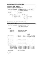
SPIM-T
3.5.3
•
SPIM-T1
3.5.4
•
SPIM-F1
3.5.5
•
SPIM-F2
3.5.6
•
SPIM-C
3.5.7
•
SPIM-A
3.5.8
3.5.1 Connecting the Network Port Cabling (MRX/MRXI)
The MRX and MRXI Network Port cabling uses a 50-pin Champ
connector to attach up to twelve unshielded twisted pair segments to
the HUB. The Network feeder cable typically connects to a punch-
down block using a 50-pin Champ connector, but in some cases the
connection could require wiring the block for the individual twisted
pairs. The Appendix provides a guide to wiring the punch-down
block when a 50-pin Champ connector is not being used.
3.5.2 Connecting the Network Port Cabling (MRX-2/MRXI-2)
The MRX-2 and MRXI-2 Network Port consists of 12- RJ-45
connectors, used to attach up to twelve unshielded twisted pair
segments to the HUB. The X associated with each port number
indicates that the port is internally crossed over.
NOTE: The X indicating crossover is omitted on some units.
However, the RJ-45 Network ports are internally crossed over.
1.
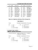
Connect twisted pair segments (see Figure 3-7) to the HUB
Network Port by inserting the RJ-45 connector from each twisted
pair segment into the desired RJ-45 port number on the HUB.
Summary of Contents for MRX
Page 11: ...INTRODUCTION Page 1 6...

