Tighten the retaining screws on each WAN port cable connector and the
Console port cable connector. If attaching a Thick Ethernet cable to the
AUI port, note that the connector has a slide latch. Snap the latch over the
posts on the cable connector to lock it in place.
If the assembly is rack mounted, secure the cables to the sides of the ver-
tical rails or to a horizontal bar or rail with cable ties, to provide strain
relief to the cable connectors.
WAN ports 0-7 provide the following interfaces:
* If the optional CSU/DSU port is used, WAN port 1 is not functional.
DCE cables have female connectors at the user end, and DTE
cables have male connectors.
Installation & Setup Guide
7
The cable connected to the Console Port depends on what device is at the
other end of the cable, as shown in Figure 1 through Figure 3.
6. Make sure the AC power switch on the rear of the FRX4000 (see Figure
7) is Off. (The switch is off when the left side is depressed.) This is simply
to assure the FRX4000 will not start before you are ready.
7. Plug the other ends of the cables into the appropriate devices: modems,
user devices, other FRX4000s, extender cables, AC receptacle.
Secure each connector by the appropriate means. Note that each WAN
port cable has retaining screws to secure it to another cable or device. The
mating connector should have threaded (4-40) stand-offs to accept the
screws. If it does not, wrap the connection with cable ties, electrical tape,
or something else that will ensure a secure fit.
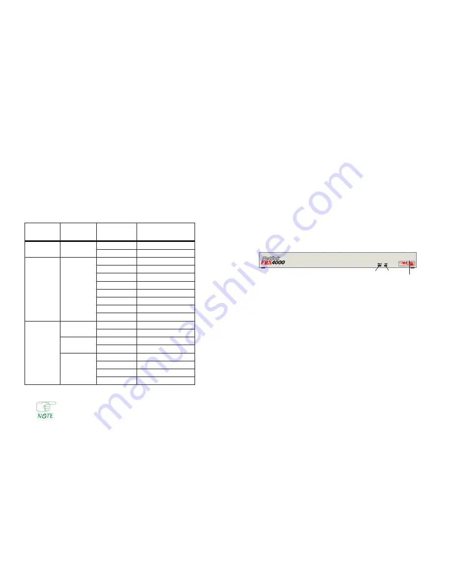
8. Switch on the terminal (if necessary), then the FRX4000. The FRX4000's
green Power light should come on.
Figure 8 LEDs
9. As the FRX4000 boots (starts), a series of messages will be displayed,
tracking the loading of the software. These messages are written to a file
named BOOTRPT.TXT. If there appears to be a problem during boot-up,
the contents of this file can be displayed (as described later), to help
determine the problem.
When the boot process is complete, a screen similar to Figure 9 will be dis-
played. (No status will be shown until the software is configured.)
8
FRX4000
Table 1 WAN Port Cables
Port
Number
Type of
Connector
Interface
with Cable
5-foot I/O Cable:
Cabletron Number
WAN 0, 1 *
RS-232
RS-232 DTE
FRX4-DTED25-CAB
RS-232 DCE
FRX4-DCED25-CAB
WAN 2, 3
Universal
RS-232 DTE
FRX4-232DTE-CAB
(HD-44)
RS-232 DCE
FRX4-232DCE-CAB
V.35 DTE
FRX4-V35DTE-CAB
V.35 DCE
FRX4-V35DCE-CAB
RS-449 DTE
FRX4-449DTE-CAB
RS-449 DCE
FRX4-449DCE-CAB
X.21 DTE
FRX4-X21DTE-CAB
X.21 DCE
FRX4-X21DCE-CAB
WAN 4–7
RS-232
RS-232 DTE
FRX-232DTE-CAB
RS-232 DCE
FRX-232DCE-CAB
V.35
V.35 DTE
FRX-V35DTE-CAB
V.35 DCE
FRX-V35DCE-CAB
RS-422
RS-449 DTE
FRX-449DTE-CAB
RS-449 DCE
FRX-449DCE-CAB
X.21 DTE
FRX-X21DTE-CAB
X.21 DCE
FRX-X21DCE-CAB
Power Fault


