SmartSTACK FAST ETHERNET SWITCH
SINGLE DC REDUNDANT POWER
SUPPLY UNIT
Cabletron System's ELS-S1DC Redundant Power
Supply Unit (RPU) can supply 150 Watts of backup
power to a single Cabletron System's SmartSTACK
ELS100-S24TX2M switch in the event of an AC loss or
failure of an internal power supply. Please check with
Cabletron Systems for information on the devices
supported by this RPU.
Features and Benefits
•
Supports one Cabletron System's SmartSTACK
ELS100-S24TX2M switch
•
AC line cord can draw power from a different supply
circuit
•
DC line cord provides backup power to the attached
device
Front and Rear Panels
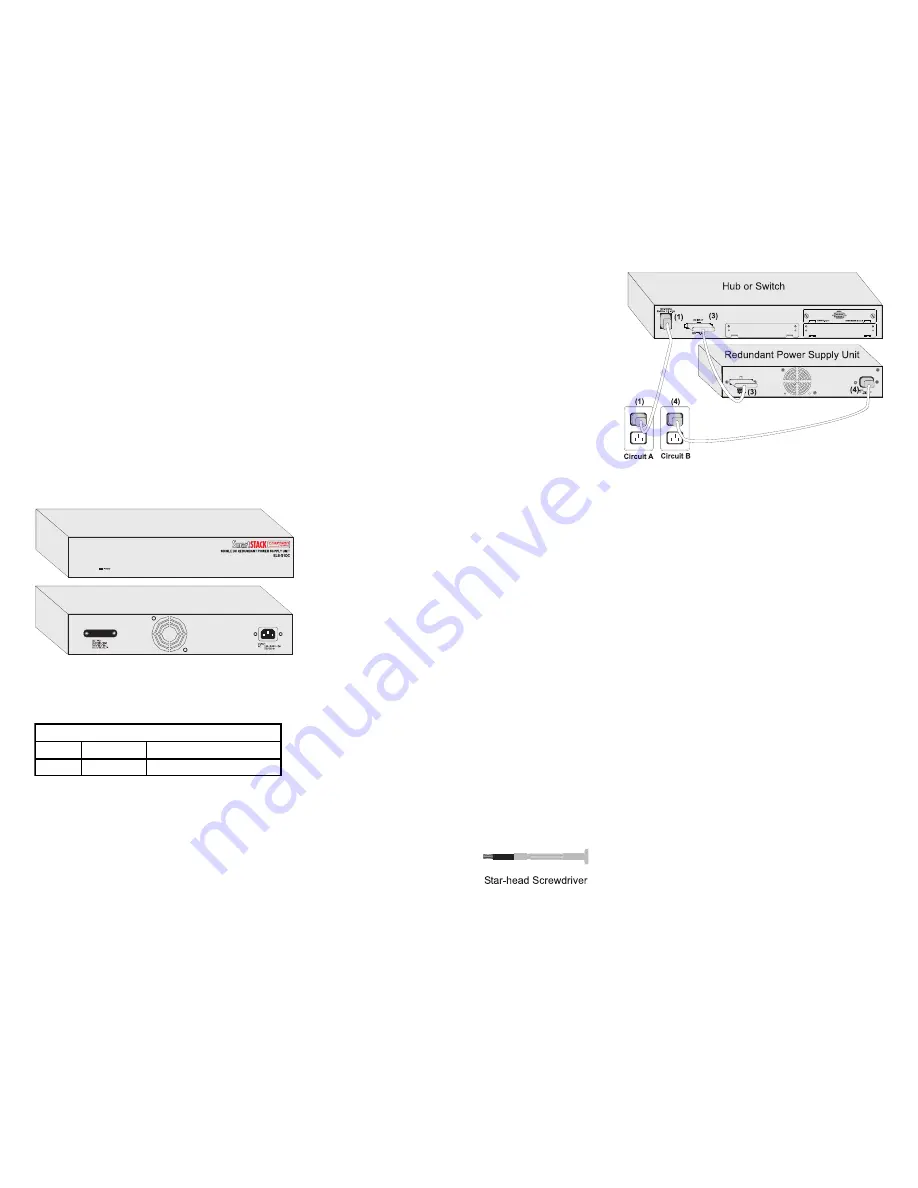
A Power indicator is located on the RPU’s front panel.
While the AC supply and DC backup receptacles are
located on the RPU’s rear panel.
The Power LED can be used to verify if this unit is
functioning properly. The following table details the
indicator function provided by the ELS-S1DC:
Status LEDs
LED
Condition
Status
Power
On
Unit is receiving power.
INSTALLING THE RPU
The RPU may be placed on a desktop or mounted in a
rack.
Warning
: DO NOT install this RPU anywhere it may
come in contact with water (i.e. floor) Cabletron
recommends that this RPU be installed in a network
rack.
Equipment Checklist
After unpacking the RPU, check the contents of the box
to be sure you’ve received the following items:
•
Redundant Power Supply Unit — provides backup
power to one Cabletron System's device
•
One AC Supply Power Cord — US, Continental
Europe or UK
•
One DC Backup Power Cord — with D-sub
connectors on both ends
•
Four Self-adhesive Rubber Feet
•
Rack Mounting Kit — brackets and screws
•
Star-head screwdriver
•
Quick Installation Guide
Desktop or Rack Mounting
You can set the RPU on a desktop or flat surface near
a separate AC power source and close to the device to
which it is to supply power. Make sure that the
mounting surface can safely support the RPU device
and that there is adequate space around the RPU for
ventilation and cooling.
The ELS-S1DC RPU ships with four (4) rubber feet.
Stick the self-adhesive rubber foot pads on each of the
four concave spaces located on the bottom of the RPU.
The rubber foot pads cushion the RPU against shock/
vibrations and provide space between each device for
ventilation.
To mount the RPU in a standard EIA 19-inch rack, use
the brackets and screws supplied with the RPU. Use a
cross-head screwdriver to attach the brackets to the
side of the RPU. Position the RPU in the rack by lining
up the holes in the brackets with the appropriate holes
on the rack. And then use the supplied screws to mount
the RPU in the rack. (Leave about two inches of space
at the rear of the RPU to ensure adequate ventilation.)
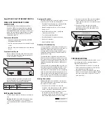
Making Connections
Caution:
DO NOT connect the RPU to an AC power
source until the DC power cord has been connected to
the other device (hub or switch).
1. Connect one end of the AC cord to the AC
receptacle on the supported device (hub or switch),
and the other end to a grounded power outlet.
2. Use the provided star-head screwdriver to loosen
the faceplate screws on the RPU’s output
receptacle and remove the faceplates from both the
RPU and the supported device (hub or switch).
3. Connect one end of the DC cord to the redundant
power receptacle on the other device (hub or
switch), and the other end to the output receptacle
on the RPU.
4. Connect one end of the AC cord to the AC
receptacle on the RPU, and the other end to a
grounded power outlet. The Power LED on the
RPU should light up.
TROUBLESHOOTING
If you experience any problems with the RPU, check
the following items before contacting Cabletron
Systems Technical Support:
•
Ensure that the RPU in the stack is powered up.
•
Ensure that the devices attached to the stack are
powered up and operating correctly.
•
Check the connectors on both ends of the power
cable to be sure they are properly engaged. Tighten
the screws on the cable connectors to ensure a
good connection.


