SBU128
User Manual
80-10200000-01
2–6
2.4.5 ISDN
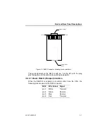
The following links when fitted to the ISDN pcb, apply a 100 ohm
termination to the ISDN transmit and receive pairs as follows:-
Shorting Link
Pair
JP1
Receive
JP2
Transmit
These links may need to be inserted when a longer S-bus line length is
used.
2.5 Command Terminal Access
Software configuration and control of your SBU128 is achieved via the
Command port on the rear panel, using a local terminal, modem or PC.
The port is configured as a physical DCE, the terminal standard is
VT100, with data transfer at 9600 bit/s, no parity, 8 data bits, 1 start and
1 or 2 stop bits. This data rate can be altered by software command. No
terminal emulation is used.
There is no hardware configuration to the Command port.
2.6 Non Volatile Options
These options are “non-volatile” because they are not defaulted when a
factory default is performed. However the first “A” option in each sub-
menu is the preferred setting that is naturally set (by virtue of all “1”s in
the RAM locations) when the unit is built, unless specifically changed for
the country of destination.
2.6.1 Product and Network Variants
Different operational modes can be selected with the Product Variants
menu. Different Network Variants can be selected allowing several
different countries and product variants to use the same software held in
FLASH memory.
Both these variants can be changed via the Non Volatile Options menu,
obtainable by typing the letter ‘K’ at the top level menu. The correct
variants are set for the destination country and application before
shipping.
Summary of Contents for SmartSwitch SBU128
Page 3: ...SBU128 User Manual 80 10200000 01 iii History Sheet 80 10200000 01 V1 00 Software 31 July 1998...
Page 74: ...SBU128 User Manual 80 10200000 01 11 2 11 1 Configuration Menu...
Page 75: ...Command Maps 80 10200000 01 11 3...
Page 76: ...SBU128 User Manual 80 10200000 01 11 4 11 2 Operation Menu...


