background image


REQUIREMENTS AND SPECIFICATIONS


2-5


2.2

OPERATING SPECIFICATIONS


This section contains the specifications, power supply 
requirements, and environmental guidelines for the TPT. 
Cabletron Systems reserves the right to change these 
specifications at any time without notice.

The TPT is designed and manufactured in accordance with 
the IEEE 802.3 10BASE-T standard.


INTERFACE CONNECTIONS                    


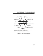
Figure 2-1 shows the pin connections for the 
RJ-45 receptacle on the TPT. Figure 2-2 shows the pin 
configuration of the AUI connecter. 

Summary of Contents for TPT

Page 1: ...TPT 10BASE T TWISTED PAIR TRANSCEIVER USER S MANUAL CABLETRON SYSTEMS P O Box 5005 Rochester NH 03867 5005...

Page 2: ......
Page 3: ...SEQUENTIAL DAMAGES WHATSOEVER INCLUDING BUT NOT LIMITED TO LOST PROFITS ARISING OUT OF OR RELATED TO THIS MANUAL OR THE INFORMATION CONTAINED IN IT EVEN IF CABLETRON SYSTEMS HAS BEEN ADVISED OF KNEW O...

Page 4: ...e If this equipment does cause interference to radio or television which can be determined by turning the equipment off and on the user is encouraged to try to correct the interference by one or more...

Page 5: ...RANSCEIVER 1 3 CHAPTER 2 REQUIREMENTS AND SPECIFICATIONS 2 1 NETWORK DESIGN GUIDELINES 2 1 2 2 OPERATING SPECIFICATIONS 2 5 CHAPTER 3 INSTALLING THE TPT 3 1 UNPACKING THE TPT 3 1 3 2 MOUNTING THE TPT...

Page 6: ...Contents iv 3 3 3 Connecting the TPT to a Twisted Pair Segment 3 5 3 3 4 Providing Strain Relief 3 8 CHAPTER 4 TESTING AND TROUBLESHOOTING 4 1 INSTALLATION CHECK OUT 4 1 4 2 USING LANVIEW 4 3...

Page 7: ...et network You should read this manual thoroughly to fully understand the TPT and its capabilities 1 1 USING THIS MANUAL Chapter 1 Introduction is an overview of the TPT 10BASE T Twisted Pair Transcei...

Page 8: ...Ds and how you can use them to troubleshoot network problems Before you install the TPT you should have a general working knowledge of Ethernet or IEEE 802 3 type data communications networks and thei...

Page 9: ...can connect it by means of an AUI cable The TPT fully conforms to IEEE 802 3 10BASE T specifications and guarantees the flexibility to connect to networks using IEEE 802 3 or Ethernet Version 1 or 2 e...

Page 10: ...rtbeat test function With SQE Test turned on the transceiver generates a test signal after each packet transmission that checks the collision circuit and path between the TPT and the device attached t...

Page 11: ...ncorporates Cabletron Systems LANVIEW diagnostic and monitoring system LANVIEW gives a visual indication of problems such as power failures collisions and cable faults LANVIEW can alert you to a probl...

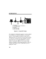
Page 12: ...closet the twisted pair segment is connected to Cabletron Systems 10BASE T Twisted Pair Media Interface Module TPMIM in a Multi Media Access Center MMAC 6 In this config uration a 10BASE T twisted pa...

Page 13: ...and power requirements Review all specifications guidelines and requirements in this chapter before you install the TPT You must meet all these conditions to ensure satisfactory performance of your ne...

Page 14: ...uation cables may be required for links of greater than 126 meters Due to cable delay themaximum link length is always limited to about 200 meters regardless of the cable type Insertion Loss The maxim...

Page 15: ...rate more than 5 0 ns of jitter If your cable meets the impedance requirements for a 10BASE T link jitter should not be a concern Delay The maximum propagation delay of a 10BASE T link segment must no...

Page 16: ...te the cable or eliminate the source of the impulse noise Temperature Most multi pair PVC 24 AWG telephone cables typically have an attenuation of approximately 8 to 10 dB 100 m at 20 C 68 F The atten...

Page 17: ...ines for the TPT Cabletron Systems reserves the right to change these specifications at any time without notice The TPT is designed and manufactured in accordance with the IEEE 802 3 10BASE T standard...

Page 18: ...REQUIREMENTS AND SPECIFICATIONS 2 6 Figure 2 1 RJ 45 Pin Connections Pin 1 TX Pin 2 TX Pin 3 RX Pin 4 No Connection Pin 5 No Connection Pin 6 RX Pin 7 No Connection Pin 8 No Connection 1 2 3 4 5 6 8 7...

Page 19: ...Logic Ref 2 Collision 3 Transmit 4 Logic Ref 5 Receive 6 Power Return 7 No Connection 8 Shield 9 Collision 10 Transmit 11 Shield 12 Receive 13 Power 12VDC in 14 Shield 15 No Connection Type 15 Positi...

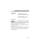
Page 20: ...WER SUPPLY Parameter Typical Worst Value Case Input Voltage 12 V 9 5 to 15 V Total Current Draw 170 mA 210 mA max ENVIRONMENTAL Non operating Temperature 30 to 80 C Operating Temperature 5 to 60 C Ope...

Page 21: ...Hz 5 V m Electromagnetic Radiation Meets FCC part 15 Class A Limits SAFETY Designed in accordance with UL478 UL910 NEC725 2 b CSA IEC TUV VDE Class A Meets FCC part 15 Class A limits WARNING It is the...

Page 22: ...REQUIREMENTS AND SPECIFICATIONS 2 10 PHYSICAL Dimensions 9 9 x 4 1 x 2 0 cm 3 7 x 1 6 x 8 in Weight 68 gm 15 lb...

Page 23: ...ations are met before you install the TPT 3 1 UNPACKING THE TPT To unpack the transceiver 1 Remove the accessory bag from the shipping box and make sure it contains the following one set of Velcro mou...

Page 24: ...t to be easily connected to the transceiver Allows an AUI cable to be easily connected to the transceiver Has a smooth dirt free surface that will accept the adhesive bonds Mount the TPT as follows 1...

Page 25: ...ets you enable or disable the SQE test function The SQE switch is the two position slide switch on top of the TPT CAUTION You must disable the SQE test function if you are connecting the transceiver t...

Page 26: ...f the TPT 3 3 2 Connecting the TPT to an Ethernet Device The TPT connects directly to an Ethernet device through an AUI connection You can either connect the TPT directly to the device or use an AUI c...

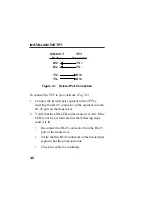
Page 27: ...sted Pair Segment The physical communication link consists of two pairs of wires the first pair is the Transmit Pair TX TX the second pair is the Receive Pair RX RX The Transmit Pair of the TPT transc...

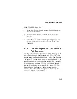
Page 28: ...T by inserting the RJ 45 connector on the segment into the RJ 45 port on the transceiver 2 Verify that the LNK LED on the transceiver is lit If the LED is not lit perform each of the following steps u...

Page 29: ...chnical Support NOTE If link has been established but the LNK LED flashes on and off the polarity of the cable is reversed in the receive pair of the twisted pair segment The TPT has a self correcting...

Page 30: ...e maximum strain relief to the cables support should be provided about 4 from the TPT 4 s RJ 45 port and if necessary near the end of the built in AUI cable extending from the TPT 4 2 Peel off the pap...

Page 31: ...ction contains procedures to test the TPT to ensure that it is operating properly For the procedures in this section you will need two Ethernet node testers such as the Cabletron Systems LAN MD that a...

Page 32: ...allation Checkout 4 Select and run test 6 SERVER on the LAN MD connected in step 1 Verify that the status on the LAN MD is 000 if SQE is on or 001 if SQE is off a PASS TEST STATUS LED is lit on the LA...

Page 33: ...nd sent back from the SERVER LAN MD that was left running on the other segment When the TPT has passed the NODE test it is ready for normal operation If any failures are noted please contact Cabletron...

Page 34: ...n If the PWR LED is not lit power is not being received from the device or the DC to DC converter in the transceiver has failed Figure 4 2 LANVIEW LEDs Signal Quality Error SQE or Heartbeat Test Funct...

Page 35: ...off if the device is active but not transmitting data onto the network Receive RCV LED This yellow LED flashes when the transceiver receives data from the network If the transceiver is attached to a d...

Page 36: ...h the polarity reversed The TPT will operate normally due to the Polarity Detection and Correction feature If no data has been sent for 20 ms a positive link test pulse of 100 ns is sent onto the tran...

Reviews: